HS50_advance_level 1_20200522_221201 (1).pdf - 第136页
06/2002 E dition Studen t Guide H S-50 Advance d I 5 DLM1 C&P H ead 44 5 Ab b. 5. 4 - 8 Re pl acin g t he s tar (1) Sleeve (2) S tar , moun ted / DLM 1 (3) S tar drive (4) Front part of r evo lver he ad (5) M3x8 hex …

Student Guide HS-50 Advanced I 06/2002 Edition
5 DLM1 C&P Head
43
➠ Carefully push the camera against the revolver head until the camera plinth is lying flat on the
contact surfaces on the front part of the revolver head.
➠ Use the four M4x10 hexagon socket-head screws to fix the camera in place (see item 6 in Fig.
5.4 - 7
).
➠ Connect the ribbon cable to socket X3 on the "component illumination" board (item X3 in
Fig. 5.4 - 7
).
➠ Fit the front part of the revolver head as described in section 5.4.3.3, page 5 - 39.
➠ Fix the head cover in place.
5.4.4.5 Settings
➠ Start the placement system.
➠ Use the SITEST program to calibrate the revolver head.
5.4.5 Removal of star
5.4.5.1 Tools and equipment
– Set of DIN 911 Allen keys
– Gauge for the star (revolver head / DLM1), article number 00326164-01
– Power pack for the revolver head / DLM1, article number 00353277-01
– Tray for transporting the revolver head
– Laboratory gloves
5.4.5.2 Parts
Star, mounted / DLM1, article number 00341181-01 5
5.4.5.3 Dismantling the star
➠ Dismantle the front part of the revolver head as described in section 5.4.3, page - 36 onwards.
➠ Place the front part of the revolver head on the tray.
PLEASE NOTE:
Wear laboratory gloves when you remove the sleeves from the star. 5
➠ Remove all the sleeves (item 1 in Fig. 5.4 - 8) and place them in the sleeve box or on a soft,
clean surface.
➠ Loosen the three M3x8 hexagon socket head screws (item 5 in Fig. 5.4 - 8).
➠ Raise the star slightly.
➠ Use a rotary movement to lift the star up and off.
06/2002 Edition Student Guide HS-50 Advanced I
5 DLM1 C&P Head
44
5
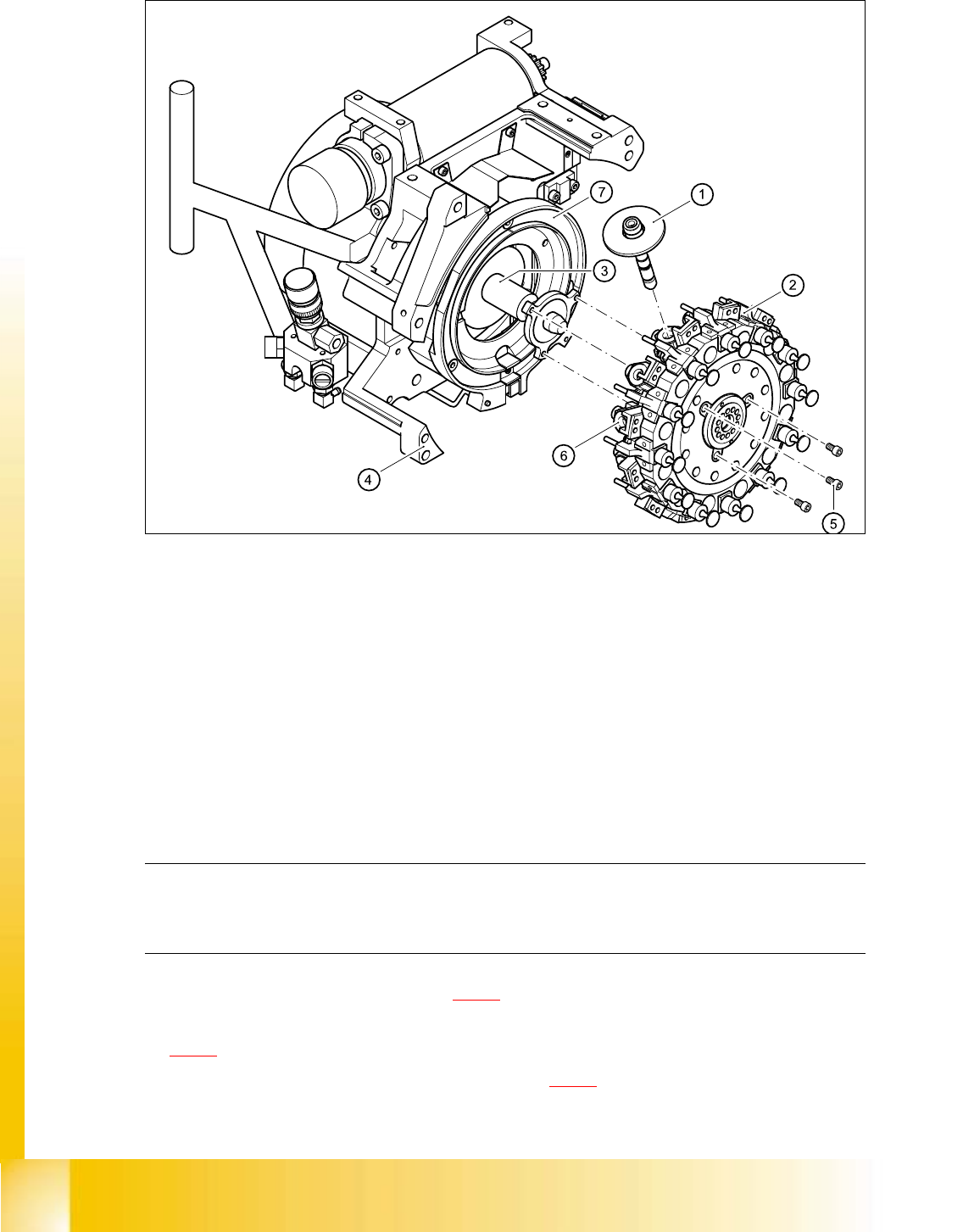
Abb. 5.4 - 8 Replacing the star
(1) Sleeve
(2) Star, mounted / DLM1
(3) Star drive
(4) Front part of revolver head
(5) M3x8 hexagon socket head screws, 3x
(6) Segment
(7) Raceway
5.4.5.4 Fitting the star
PLEASE NOTE:
Remove any remaining sleeves before fitting the star.
Wear laboratory gloves when removing the sleeves. 5
➠ Push all the segments (item. 6 in Fig. 5.4 - 8) slightly outwards.
➠ Insert small Allen keys (e.g. size 2) into the holes for the star fixing screws (item 5 in Fig.
5.4 - 8
).
➠ Hold the star over the star drive shaft (item 3 in Fig. 5.4 - 8) so that the Allen keys slide into the
threaded holes in the star drive.

Student Guide HS-50 Advanced I 06/2002 Edition
5 DLM1 C&P Head
45
➠ Push all the segments outwards.
➠ Insert the star.
PLEASE NOTE:
Make sure that the vacuum hoses of the segments do not become squashed. 5
➠ Push all the segments inwards so that the segment ball bearings slide into the raceway (item
7 in Fig. 5.4 - 8
).
➠ Check that the star is seated flat on the drive shaft.
➠ Loosely tighten the three M3x8 hexagon socket head screws on the star so that the screws can
still move slightly in the fixing holes.
5.4.5.5 Adjusting the star with respect to the star's magnetic neutral position.
The aim of adjusting the star is to ensure that the vertical axis of segment no. 1 is aligned with the
magnetic neutral position of the star step motor. 5
➠ To do this, insert the gauge pin into the gauge for the star and into the hole in the segment
no. 1, until it reaches the stop.
➠ Pull off the motor line plug of the star motor from socket X5 on the intermediate distribution
board and connect the motor line to the power supply.
➠ Connect the power supply unit to main power.
➠ Tighten the three M3x8 hexagon socket head screws on the star.
➠ Remove the gauge pin.
➠ Insert the gauge pin again into the gauge for the star and into the hole in the segment, until it
reaches the stop. Then check:
– that the gauge pin can be inserted easily.
– that the star does not rotate out of its current position as a result.
If both of these conditions are fulfilled, then the star has been fitted correctly. 5
➠ Disconnect the power pack from the power source.
➠ Continue from section 5.4.3.3 "Fitting the front part of the revolver head".
➠ Repeat the adjustment procedure if the gauge pin does not slide easily into the hole.
CAUTION
The maximum operating time of the power pack for the star motor is five minutes. Do NOT
exceed this time. If you have to disconnect the power pack from the power source because
it has been operating for five minutes, always insert the gauge pin before switching the power
pack on again. 5