HS50_advance_level 1_20200522_221201 (1).pdf - 第139页
Studen t Guide HS-50 A dvanced I 06/200 2 Edition 5 DLM1 C&P Head 47 5.4. 6 Removal o f t he valve s 5.4. 6.1 T ools and e quipm ent – Set of DIN 91 1 Allen keys – S et of P hilli ps screw dri vers – SITES T program …
06/2002 Edition Student Guide HS-50 Advanced I
5 DLM1 C&P Head
46
If you still cannot fit the star in the magnetic neutral position of the star motor, follow the
instructions below: 5
➠ Loosen the four M5x16 hexagon socket head screws (item 2 in Fig. 5.4 - 9) for fixing the star
drive (item 1 in Fig. 5.4 - 9
) and turn the star drive in the direction that will allow the star to be
adjusted with respect to the magnetic neutral position. Tighten the four hexagon socket head
screws in this position.
5
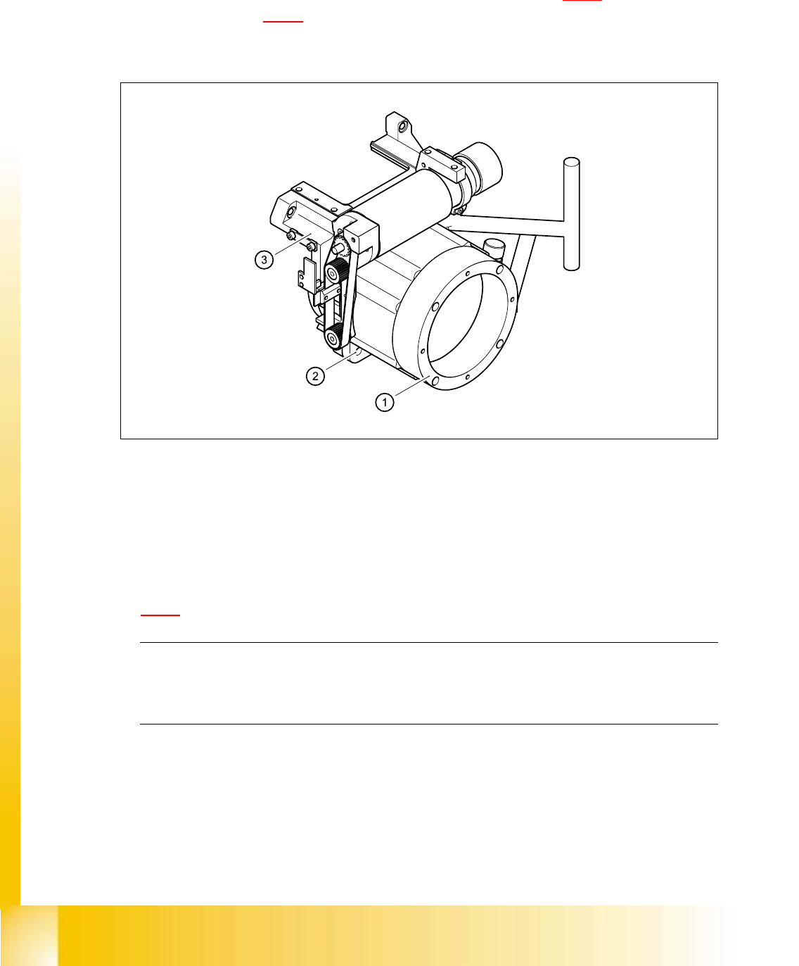
Abb. 5.4 - 9 Loosening the star drive
(1) Star drive, digital / DLM1
(2) M5x16 hexagon socket head screws, 4x
(3) Front part of revolver head
5
➠ Loosen the three M3x8 hexagon socket head screws (item 5 in Fig.
5.4 - 8
) for fixing the star again and repeat the adjustment procedure.
PLEASE NOTE:
The star is fitted correctly until it no longer moves out of position when the gauge pin is
removed after disconnecting the star drive from the power supply. 5

Student Guide HS-50 Advanced I 06/2002 Edition
5 DLM1 C&P Head
47
5.4.6 Removal of the valves
5.4.6.1 Tools and equipment
– Set of DIN 911 Allen keys
– Set of Phillips screwdrivers
– SITEST program
– Feeler gauge, item no. 00325445-01
5.4.6.2 Parts
Valve positioning drive, placement circuit, item no. 00349433-01 (Pos. 1 in Fig. 5.4 - 10)
Valve positioning drive, reject circuit, item no. 00349432-01 (Pos. 2 in Fig. 5.4 - 10
) 5
5.4.6.3 Dismantling the valve positioning drive
➠ Remove the revolver head from the head mount (see section 5.4.12.3, page 5 - 69).
➠ Loosen the two M2x6 Phillips screws on the ribbon cable clamp (items 3 and 4 in Fig. 5.4 - 10).
➠ Loosen the M3x10 hexagon socket-head screw (item 4 in Fig. 5.4 - 10).
➠ Carefully remove the valve positioning drive (item 1 or 2 in Fig. 5.4 - 10).
06/2002 Edition Student Guide HS-50 Advanced I
5 DLM1 C&P Head
48
5
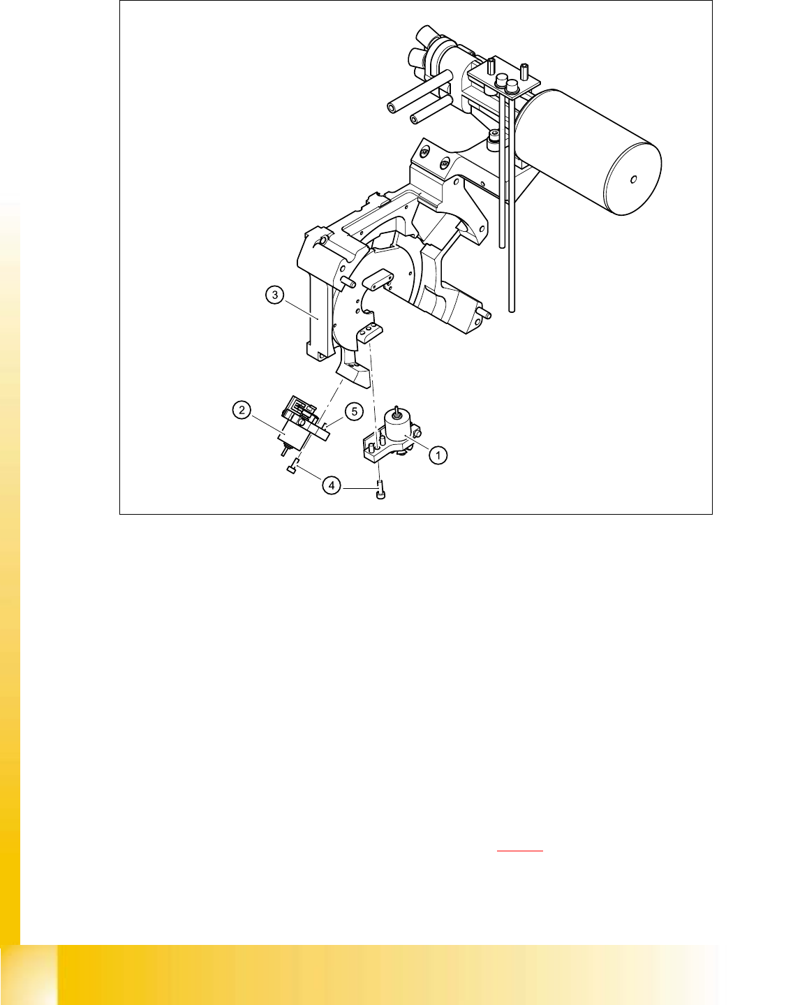
Fig. 5.4 - 10 Replacing the valve positioning drive
(1) "Placement circuit" valve positioning drive
(2) "Reject circuit" valve positioning drive
(3) Back part of the revolver head
(4) M3x10 hexagon socket-head screw
(5) Parallel pins, 2 x per drive
5.4.6.4 Fitting the valve positioning drive
➠ Insert the valve positioning drive, making sure that it is seated correctly on the parallel pins.
➠ Loosely tighten the hexagon socket-head screw.
➠ Use the cable clamp assemblies (items 2, 3, and 4 in Fig. 5.4 - 11) to fix the ribbon cables in
position, ensuring that the ribbon cables are not squashed.