HS50_advance_level 1_20200522_221201 (1).pdf - 第140页
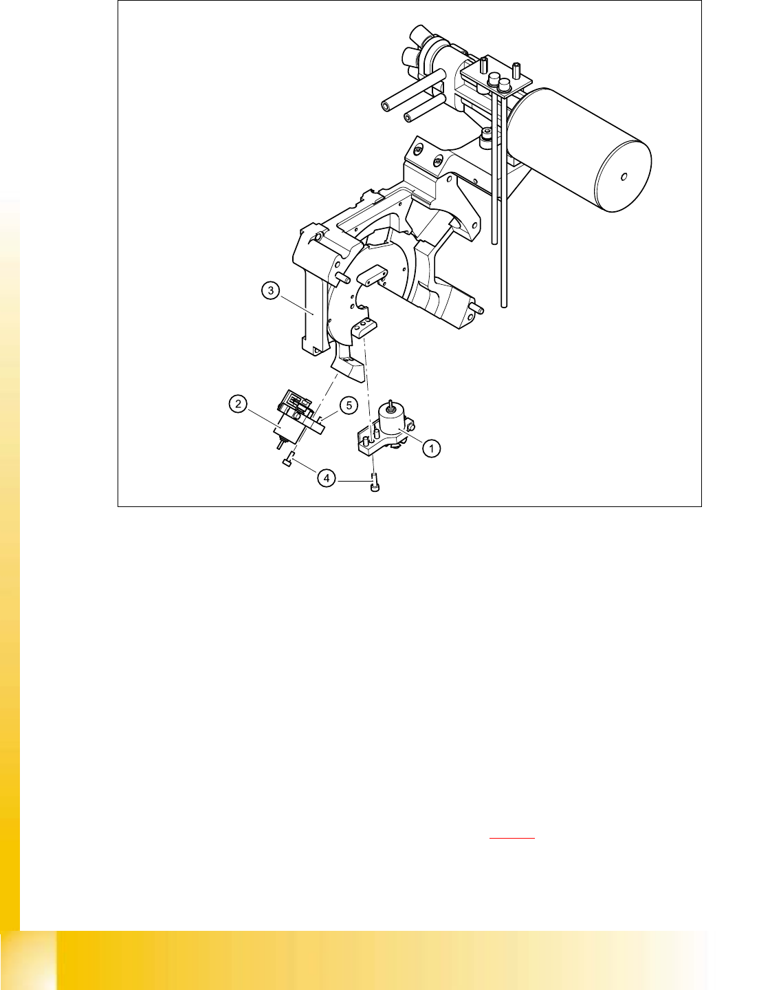
06/2002 E dition Studen t Guide H S-50 Advance d I 5 DLM1 C&P H ead 48 5 F ig. 5. 4 - 10 Re plac in g th e v alv e p osit io ning dri ve (1) "Placeme nt circuit" v alve positioning drive (2) "Reject ci…

Student Guide HS-50 Advanced I 06/2002 Edition
5 DLM1 C&P Head
47
5.4.6 Removal of the valves
5.4.6.1 Tools and equipment
– Set of DIN 911 Allen keys
– Set of Phillips screwdrivers
– SITEST program
– Feeler gauge, item no. 00325445-01
5.4.6.2 Parts
Valve positioning drive, placement circuit, item no. 00349433-01 (Pos. 1 in Fig. 5.4 - 10)
Valve positioning drive, reject circuit, item no. 00349432-01 (Pos. 2 in Fig. 5.4 - 10
) 5
5.4.6.3 Dismantling the valve positioning drive
➠ Remove the revolver head from the head mount (see section 5.4.12.3, page 5 - 69).
➠ Loosen the two M2x6 Phillips screws on the ribbon cable clamp (items 3 and 4 in Fig. 5.4 - 10).
➠ Loosen the M3x10 hexagon socket-head screw (item 4 in Fig. 5.4 - 10).
➠ Carefully remove the valve positioning drive (item 1 or 2 in Fig. 5.4 - 10).
06/2002 Edition Student Guide HS-50 Advanced I
5 DLM1 C&P Head
48
5
Fig. 5.4 - 10 Replacing the valve positioning drive
(1) "Placement circuit" valve positioning drive
(2) "Reject circuit" valve positioning drive
(3) Back part of the revolver head
(4) M3x10 hexagon socket-head screw
(5) Parallel pins, 2 x per drive
5.4.6.4 Fitting the valve positioning drive
➠ Insert the valve positioning drive, making sure that it is seated correctly on the parallel pins.
➠ Loosely tighten the hexagon socket-head screw.
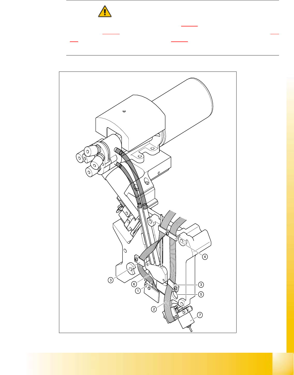
➠ Use the cable clamp assemblies (items 2, 3, and 4 in Fig. 5.4 - 11) to fix the ribbon cables in
position, ensuring that the ribbon cables are not squashed.
Student Guide HS-50 Advanced I 06/2002 Edition
5 DLM1 C&P Head
49
CAUTION 5
Check that the ribbon cables (item 1 and 2 in Fig. 5.4 - 11
) are laid correctly. The ribbon cable
(item 2 in Fig. 5.4 - 11
) from the valve adjustment unit to the reject station (item 6 in Fig. 5.4
- 11) must run outside the hole (item 5 in Fig. 5.4 - 11), otherwise it will be damaged when the
revolver head is fitted on the head mount. 5
5
Fig. 5.4 - 11 Laying the ribbon cables for the valve adjustment drives