HS50_advance_level 1_20200522_221201 (1).pdf - 第143页
Studen t Guide HS-50 A dvanced I 06/200 2 Edition 5 DLM1 C&P Head 51 ➠ Use the feeler gauge to set the distance between the valve plunger and valve casing to 0.2 mm (item A in Fig. 5. 4 - 12 ). ➠ T urn the adjusting …
06/2002 Edition Student Guide HS-50 Advanced I
5 DLM1 C&P Head
50
Key to Fig. 5.4 - 11
(1) Flat ribbon cable for the ’Placement’ valve adjustment unit
(2) Flat ribbon cable for the ’Reject circuit’ valve adjustment unit
(3) Cable clamp assembly
(4) Cable clamp assembly
(5) Hole
(6) ’Placement’ valve adjustment unit
(7) ’Reject circuit’ valve adjustment unit
5
5.4.6.5 Mechanical adjustment
5
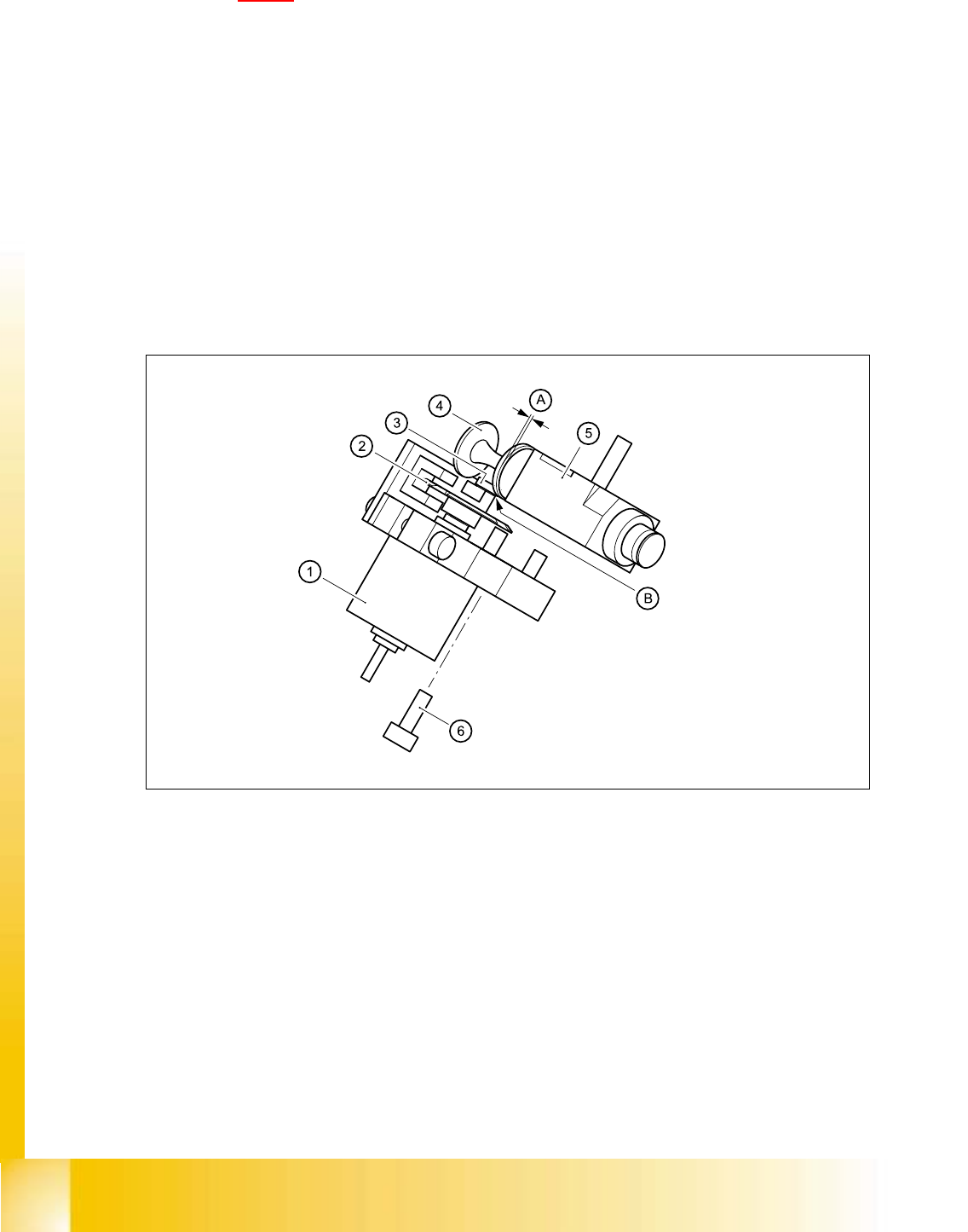
Fig. 5.4 - 12 Mechanical adjustment of the valve positioning drives
(1) Stepping motor
(2) Adjusting disk
(3) Deep-groove ball bearings
(4) Valve plunger
(5) Valve casing
(6) M3x10 hexagon socket-head screw
5
5

Student Guide HS-50 Advanced I 06/2002 Edition
5 DLM1 C&P Head
51
➠ Use the feeler gauge to set the distance between the valve plunger and valve casing to 0.2 mm
(item A in Fig. 5.4 - 12
).
➠ Turn the adjusting disk (see item 2 in Fig. 5.4 - 12) until the deep-groove ball bearings (item 3
in Fig. 5.4 - 12
) point towards the valve casing.
➠ Move the valve adjustment drive (item 6 in Fig. 5.4 - 12) so that the deep-groove ball bearings
(item 3 in Fig. 5.4 - 12
) come into contact with the valve plunger (item 4 in Fig. 5.4 - 12) at po-
sition B.
➠ Use the hexagon socket-head screw (item 6) to fix valve adjustment unit in this position.
➠ Attach the revolver head to the head mount (see section 5.4.12.4, page 5 - 72).
5.4.6.6 Settings
➠ Use the SITEST program to test that the valve positioning drive is functioning correctly.
➠ Use the SITEST program to calibrate the revolver head.
5.4.7 Replacement of z-axis top sensor
5.4.7.1 Tools and equipment
– Set of DIN 911 Allen keys
– Set of Phillips screwdrivers
– SITEST program
5.4.7.2 Parts
Light barrier ’Z-axis up’, item no. 00347297-01 5
5.4.7.3 Dismantling the z-axis top sensor
➠ Switch the placement system off and secure it to prevent switching on again as described in
section 5.4.1
, page - 32.
➠ Remove the plug from socket X10 on the intermediate distribution board (see item 10 in Fig.
5.4 - 14
, page 5 - 53).
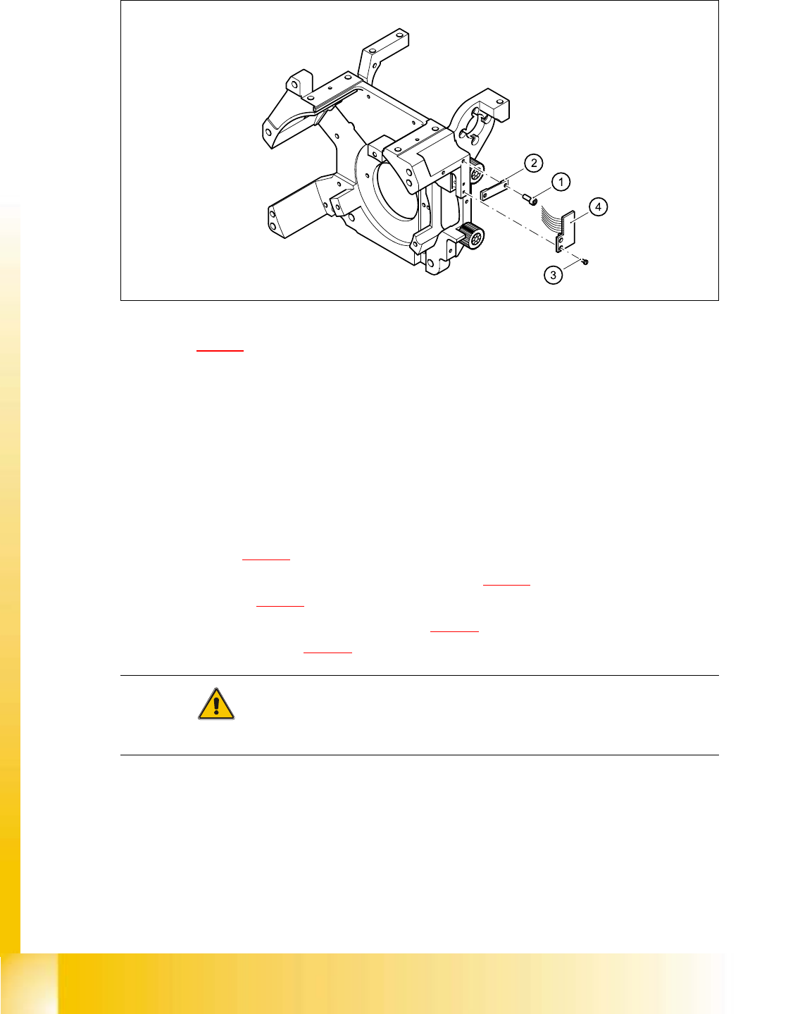
➠ Loosen the two M2.0x4 hexagon socket-head screws (see item 1 in Fig. 5.4 - 13) and remove
the ribbon cable clamp (see item 2 in Fig. 5.4 - 13
).
➠ Loosen the two M1.6x3 Phillips screws (see item 3 in Fig. 5.4 - 13).
➠ Remove the light barrier board (see item 4 in Fig. 5.4 - 13) together with its cable
06/2002 Edition Student Guide HS-50 Advanced I
5 DLM1 C&P Head
52
➠ .
Fig. 5.4 - 13 Replacing the ’Z-axis up’ light barrier board
Key to Fig. 5.4 - 13
(1) 2 x M2.0x4 hexagon socket-head screw
(2) Cable clamp assembly, flat
(3) 2 Phillips screws (1.6x3)
(4) Light barrier board ’Z-axis up’
5.4.7.4 Fitting the z-axis top sensor
➠ Connect the ribbon cable plug to socket X10 on the intermediate distribution board (see
item X10 in Fig. 5.4 - 14
).
➠ Use the two M1.6x3 Phillips screws (see item 3 in Fig. 5.4 - 13) to fix the light barrier board
(see item 4 in Fig. 5.4 - 13
) in place.
➠ Use the ribbon cable clamp (see item 2 in Fig. 5.4 - 13) and the two hexagon socket-head
screws (see item 1 in Fig. 5.4 - 13
) to fix the ribbon cables.
CAUTION 5
Make sure that the ribbon cable is not squashed in the guide channel. 5