HS50_advance_level 1_20200522_221201 (1).pdf - 第144页
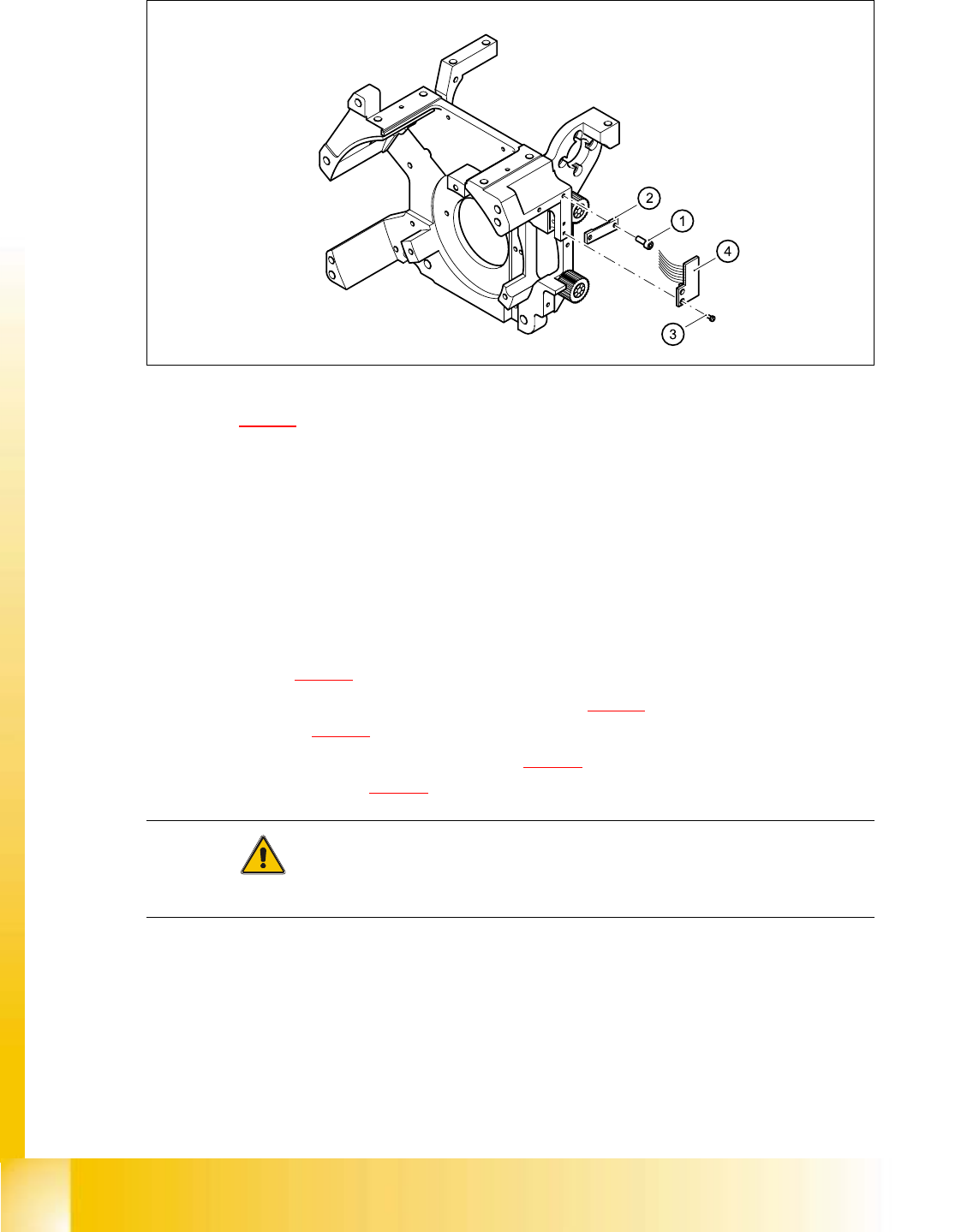
06/2002 E dition Studen t Guide H S-50 Advance d I 5 DLM1 C&P H ead 52 ➠ . F ig. 5. 4 - 13 Re pl acin g the ’ Z-a xi s up ’ l ig ht ba rr ier boa rd Key to Fig. 5.4 - 13 (1) 2 x M2.0 x 4 hex agon s ocket-head screw (…

Student Guide HS-50 Advanced I 06/2002 Edition
5 DLM1 C&P Head
51
➠ Use the feeler gauge to set the distance between the valve plunger and valve casing to 0.2 mm
(item A in Fig. 5.4 - 12
).
➠ Turn the adjusting disk (see item 2 in Fig. 5.4 - 12) until the deep-groove ball bearings (item 3
in Fig. 5.4 - 12
) point towards the valve casing.
➠ Move the valve adjustment drive (item 6 in Fig. 5.4 - 12) so that the deep-groove ball bearings
(item 3 in Fig. 5.4 - 12
) come into contact with the valve plunger (item 4 in Fig. 5.4 - 12) at po-
sition B.
➠ Use the hexagon socket-head screw (item 6) to fix valve adjustment unit in this position.
➠ Attach the revolver head to the head mount (see section 5.4.12.4, page 5 - 72).
5.4.6.6 Settings
➠ Use the SITEST program to test that the valve positioning drive is functioning correctly.
➠ Use the SITEST program to calibrate the revolver head.
5.4.7 Replacement of z-axis top sensor
5.4.7.1 Tools and equipment
– Set of DIN 911 Allen keys
– Set of Phillips screwdrivers
– SITEST program
5.4.7.2 Parts
Light barrier ’Z-axis up’, item no. 00347297-01 5
5.4.7.3 Dismantling the z-axis top sensor
➠ Switch the placement system off and secure it to prevent switching on again as described in
section 5.4.1
, page - 32.
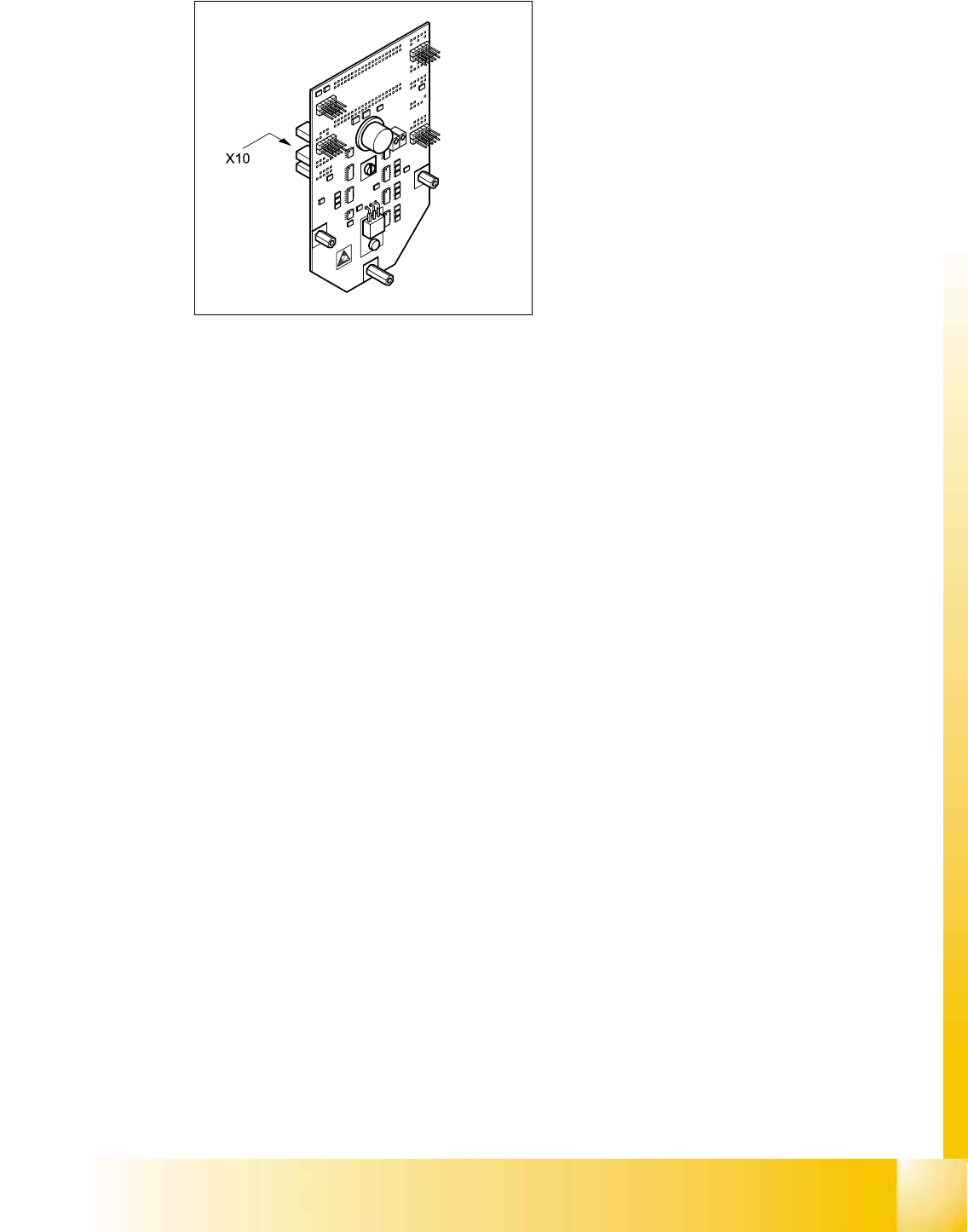
➠ Remove the plug from socket X10 on the intermediate distribution board (see item 10 in Fig.
5.4 - 14
, page 5 - 53).
➠ Loosen the two M2.0x4 hexagon socket-head screws (see item 1 in Fig. 5.4 - 13) and remove
the ribbon cable clamp (see item 2 in Fig. 5.4 - 13
).
➠ Loosen the two M1.6x3 Phillips screws (see item 3 in Fig. 5.4 - 13).
➠ Remove the light barrier board (see item 4 in Fig. 5.4 - 13) together with its cable
06/2002 Edition Student Guide HS-50 Advanced I
5 DLM1 C&P Head
52
➠ .
Fig. 5.4 - 13 Replacing the ’Z-axis up’ light barrier board
Key to Fig. 5.4 - 13
(1) 2 x M2.0x4 hexagon socket-head screw
(2) Cable clamp assembly, flat
(3) 2 Phillips screws (1.6x3)
(4) Light barrier board ’Z-axis up’
5.4.7.4 Fitting the z-axis top sensor
➠ Connect the ribbon cable plug to socket X10 on the intermediate distribution board (see
item X10 in Fig. 5.4 - 14
).
➠ Use the two M1.6x3 Phillips screws (see item 3 in Fig. 5.4 - 13) to fix the light barrier board
(see item 4 in Fig. 5.4 - 13
) in place.
➠ Use the ribbon cable clamp (see item 2 in Fig. 5.4 - 13) and the two hexagon socket-head
screws (see item 1 in Fig. 5.4 - 13
) to fix the ribbon cables.
CAUTION 5
Make sure that the ribbon cable is not squashed in the guide channel. 5
Student Guide HS-50 Advanced I 06/2002 Edition
5 DLM1 C&P Head
53
5
Fig. 5.4 - 14 Intermediate distribution board - socket X10
5.4.7.5 Settings
➠ None