HS50_advance_level 1_20200522_221201 (1).pdf - 第150页
06/2002 E dition Studen t Guide H S-50 Advance d I 5 DLM1 C&P H ead 58 5.4. 9.3 Dismantl ing the int e r me di a te distribut ion board 5 F ig. 5. 4 - 17 Di sma nt lin g the i nte rm edia te dist ri buti on boa rd Ke…

Student Guide HS-50 Advanced I 06/2002 Edition
5 DLM1 C&P Head
57
5.4.8.5 Adjusting the z-axis bottom sensor
➠ Use the test probe to set the distance between the white sleeve ring and the light barrier to 1.3
mm.
➠ Fix the light barrier in place using the two slot screws.
5.4.8.6 Fitting the star
➠ Fit and adjust the star as described in sections 5.4.5.4 and 5.4.5.5, page 5 - 44 onwards.
➠ Fit the front part of the collect&place head as described in section 5.4.3.3, page 5 - 39 onwards.
5.4.8.7 Adjustments
➠ Use the SITEST program to check that the sensor is working correctly.
5.4.9 Removal of the star motor
5.4.9.1 Tools and equipment
– Set of DIN 911 Allen keys
– Gauge for the star (collect&place head / DLM1), article number 00326164-01
– Power pack for the collect&place head / DLM1, article number 00353277-01
– Tray for transporting the collect&place head
– Laboratory gloves
5.4.9.2 Parts
Star drive, digital / DLM1, article number 00337571-01 5
06/2002 Edition Student Guide HS-50 Advanced I
5 DLM1 C&P Head
58
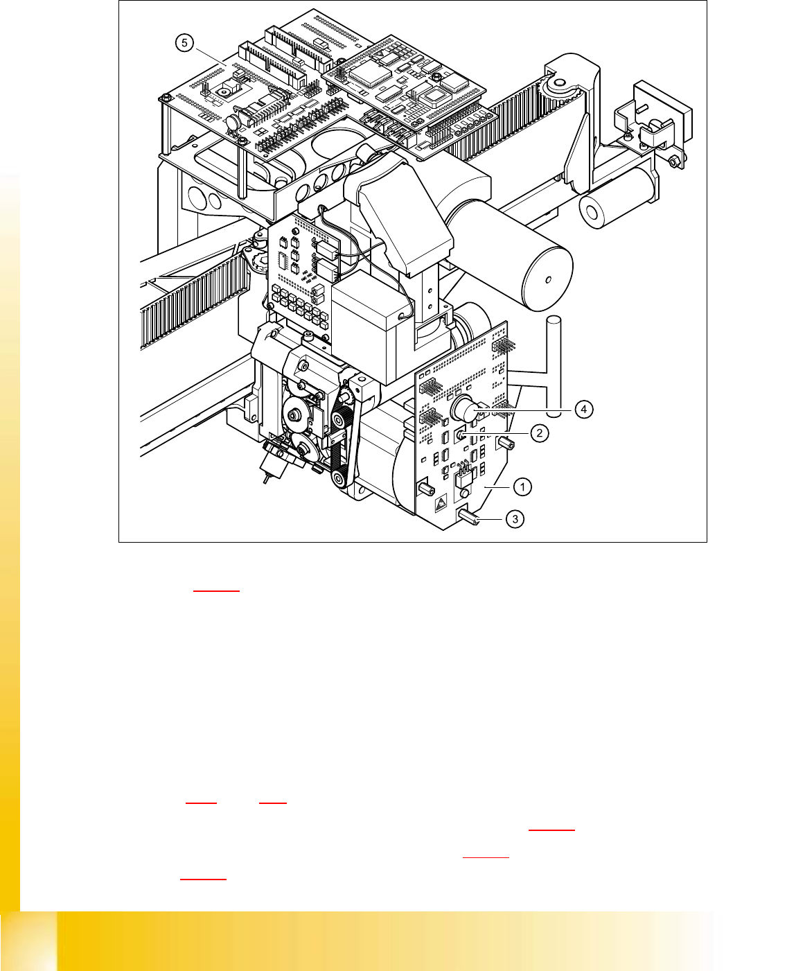
5.4.9.3 Dismantling the intermediate distribution board
5
Fig. 5.4 - 17 Dismantling the intermediate distribution board
Key to Fig. 5.4 - 17
(1) Intermediate distribution board
(2) M3x5 hexagon socket-head screw
(3) 3 x M3x10 spacer bolt
(4) Pressure sensor
(5) Head board
5
➠ Switch the placement system off and secure it to prevent switching on again as described in
section 5.4.1
, page - 32.
➠ Undo the M3x5 hexagon socket-head screw (see item 2 in Fig. 5.4 - 17).
➠ Remove the three M3x10 spacer bolts (item 3 in Fig. 5.4 - 17) and tilt the PCB slightly (item 1
in Fig. 5.4 - 17
).
Student Guide HS-50 Advanced I 06/2002 Edition
5 DLM1 C&P Head
59
➠ Carefully remove the hose from the pressure sensor (see item 4 in Fig. 5.4 - 17).
➠ Remove the following plugs from their sockets on the board (see Fig. 5.4 - 18 on page 5 - 59).
➠ Remove the intermediate distribution board.
5
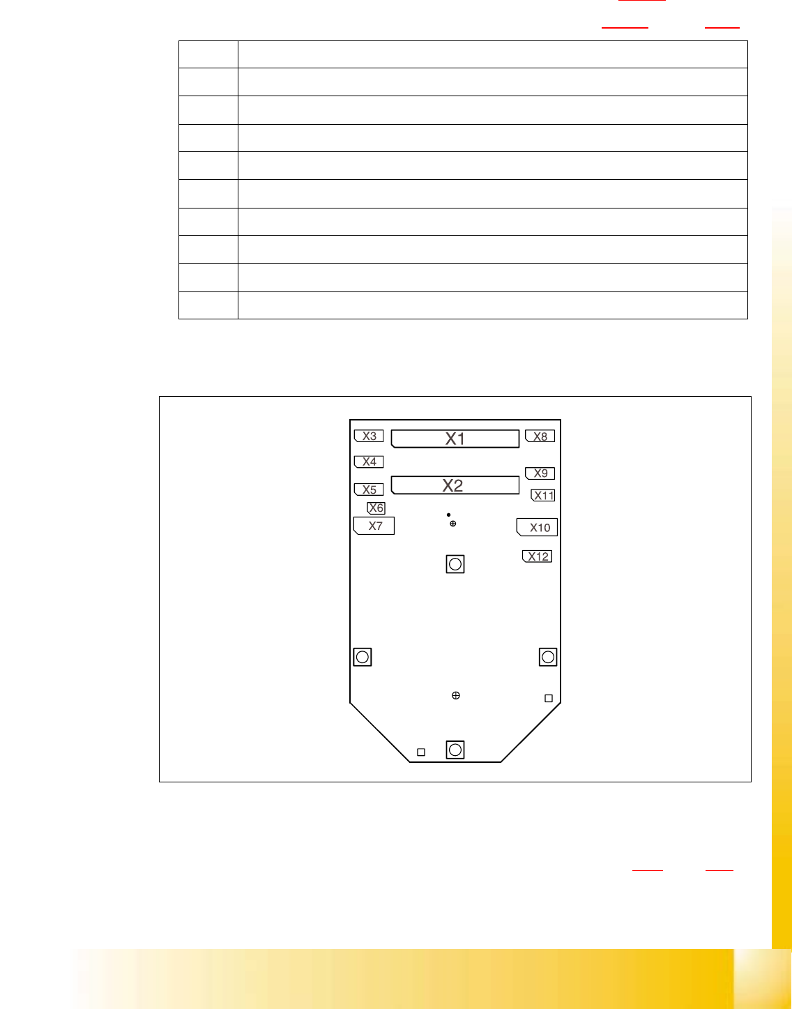
Fig. 5.4 - 18 Sockets on the intermediate distribution board
5.4.9.4 Dismantling the star
➠ Dismantle the front part of the collect&place head as described in section 5.4.3, page - 36
onwards.
➠ Place the front part of the collect&place head on the tray.
X1 Ribbon cable at X14 on the head board
X2 Ribbon cable at X13 on the head board
X3 Motor / tacho connection for the Z-axis
X4 Measuring system connection for the Z-axis
X5 Motor connection for the star axis
X6 Connection for the "Forced air unit" valve
X7 Measuring system connection for the DP-axis
X10 Connection for the "Z-axis up" light barrier (adjustment unit)
X11 Connection for the "Z-axis down" light barrier
X12 Measuring system connection for the star axis
Tab. 5.4 - 2 Sockets on the intermediate distribution board