HS50_advance_level 1_20200522_221201 (1).pdf - 第155页
Studen t Guide HS-50 A dvanced I 06/200 2 Edition 5 DLM1 C&P Head 63 CAUTION The m aximum op erating time of the p ower pack for the star mot or is five m inutes. Do NO T exceed this time. If you have to disconne c t…

06/2002 Edition Student Guide HS-50 Advanced I
5 DLM1 C&P Head
62
➠ Push all the segments (item. 6 in Fig. 5.4 - 8) slightly outwards.
➠ Insert small Allen keys (e.g. size 2) into the holes for the star fixing screws (item 5 in Fig.
5.4 - 8
).
➠ Hold the star over the star drive shaft (item 3 in Fig. 5.4 - 8) so that the Allen keys slide into the
threaded holes in the star drive.
➠ Insert the star.
PLEASE NOTE:
Make sure that the vacuum hoses of the segments do not become squashed. 5
➠ Push all the segments inwards so that the segment ball bearings slide into the raceway (item
7 in Fig. 5.4 - 8
).
➠ Check that the star is seated flat on the drive shaft.
➠ Loosely tighten the three M3x8 hexagon socket head screws on the star so that the screws can
still move slightly in the fixing holes.
5.4.9.8 Adjusting the star with respect to the star's magnetic neutral position.
The aim of adjusting the star is to ensure that the vertical axis of segment no. 1 is aligned with the
magnetic neutral position of the star step motor. 5
➠ To do this, insert the gauge pin into the gauge for the star and into the hole in the segment
no. 1, until it reaches the stop.
➠ Pull off the motor line plug of the star motor from socket X5 on the intermediate distribution
board and connect the motor line to the power supply.
➠ Connect the power supply unit to main power.
➠ Tighten the three M3x8 hexagon socket head screws on the star.
➠ Remove the gauge pin.
➠ Insert the gauge pin again into the gauge for the star and into the hole in the segment, until it
reaches the stop. Then check:
– that the gauge pin can be inserted easily.
– that the star does not rotate out of its current position as a result.
If both of these conditions are fulfilled, then the star has been fitted correctly. 5
➠ Disconnect the power pack from the power source.
➠ Continue from section 5.4.3.3 "Fitting the front part of the revolver head".
➠ Repeat the adjustment procedure if the gauge pin does not slide easily into the hole.
Student Guide HS-50 Advanced I 06/2002 Edition
5 DLM1 C&P Head
63
CAUTION
The maximum operating time of the power pack for the star motor is five minutes. Do NOT
exceed this time. If you have to disconnect the power pack from the power source because
it has been operating for five minutes, always insert the gauge pin before switching the power
pack on again. 5
If you still cannot fit the star in the magnetic neutral position of the star motor, follow the
instructions below: 5
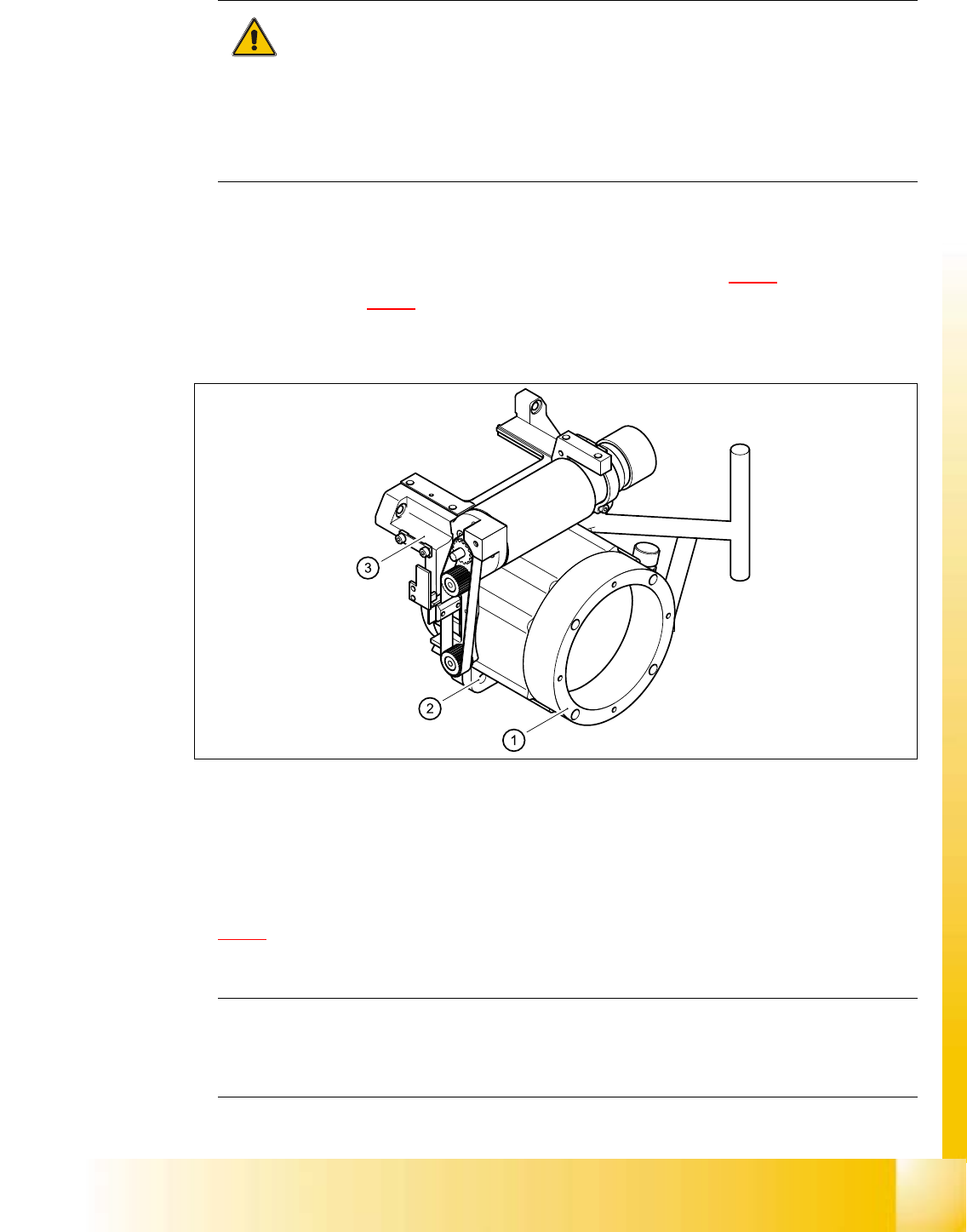
➠ Loosen the four M5x16 hexagon socket head screws (item 2 in Fig. 5.4 - 9) for fixing the star
drive (item 1 in Fig. 5.4 - 9
) and turn the star drive in the direction that will allow the star to be
adjusted with respect to the magnetic neutral position. Tighten the four hexagon socket head
screws in this position.
5
Fig. 5.4 - 21 Loosening the star drive
(1) Star drive, digital / DLM1
(2) M5x16 hexagon socket head screws, 4x
(3) Front part of collect&place head
➠ Loosen the three M3x8 hexagon socket head screws (item 5 in Fig.
5.4 - 8
) for fixing the star again and repeat the adjustment procedure.
PLEASE NOTE:
The star is fitted correctly until it no longer moves out of position when the gauge pin is
removed after disconnecting the star drive from the power supply. 5

06/2002 Edition Student Guide HS-50 Advanced I
5 DLM1 C&P Head
64
5.4.9.9 Fitting the front part of the collect&place head
➠ Remove the gauge for the star.
➠ Insert the power cable plug connector for the star drive into socket X5 on the intermediate
terminal block. The plug connector is an anti-rotation connector.
➠ Fit the front part of the collect&place head on the back part of the collect&place head (see
section 5.4.3.3
, page 5 - 39).
5.4.9.10 Fitting the intermediate distribution board
➠ Restore connections X1 ... X12 as described in Table 5.4 - 2.
➠ Push the hose onto the pressure sensor tube (see item 4 in Fig. 5.4 - 17).
➠ Fix the intermediate distribution board in place (see item 2 and 3 in Fig. 5.4 - 17).
➠ Fix the protective cover to the head.
➠ Switch the placement system on and start it up.
5.4.10 Replacing the RSF digital rotary encoder 12/DLM1
5.4.10.1 Tools and equipment
– Set of DIN 911 Allen keys
– Gauge for the star (collect&place head / DLM1), article number 00326164-01
– Test probe, 1.5 mm, article number 00326161-01
– Power pack for the collect&place head / DLM1, article number 00353277-01
– Tray for transporting the collect&place head
– Laboratory gloves
5.4.10.2 Parts
RSF digital rotary encoder 12/DLM1 article number 00335990-02 5
5.4.10.3 Dismantling the rotary encoder
– Dismantle the front part of the collect&place head as described in section 5.4.3, page - 36
onwards.
– Dismantle the star as described in section 5.4.5.3
, page 5 - 43 onwards.
– Remove the black blanking cap over the RSF board (item 4 in Fig. 5.4 - 22
).
– Remove the plug connector (item X7 in Fig. 5.4 - 22
) from socket X7 on the intermediate
terminal block.