HS50_advance_level 1_20200522_221201 (1).pdf - 第158页
06/2002 E dition Studen t Guide H S-50 Advance d I 5 DLM1 C&P H ead 66 5.4. 10.4 Fitting the rot ary encoder – Insert the new rot ary encoder and initially fix in place loosely with t he two M2.5x8 hexagon socket hea…
Student Guide HS-50 Advanced I 06/2002 Edition
5 DLM1 C&P Head
65
– Undo the two M2.5x4 hexagon socket-head screws (item 5 in Fig. 5.4 - 22) for fixing the RSF
board.
– Undo the two M2.5x8 hexagon socket-head screws (item 3 in Fig. 5.4 - 22
) and remove the
rotary encoder.
5
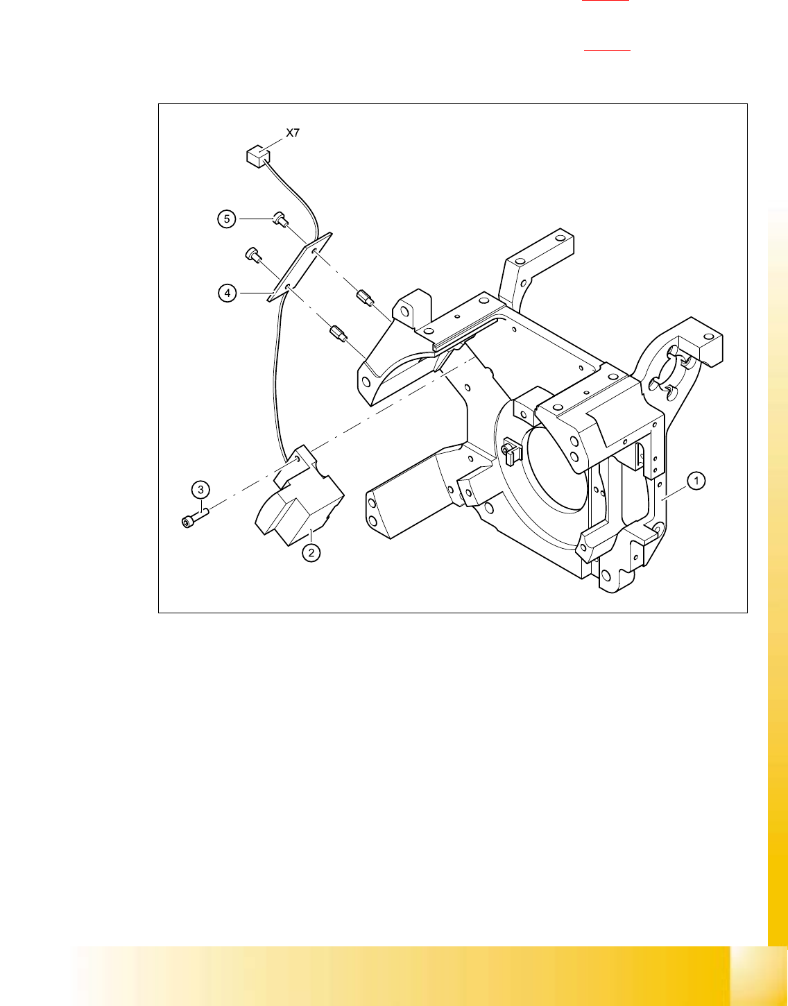
Fig. 5.4 - 22 Dismantling / fitting the rotary encoder
(1) Front part of collect&place head
(2) RSF digital rotary encoder 12/DLM1
(3) M2.5x8 hexagon socket head screws, 2x
(4) RSF board, type 950
(5) M2.5x4 hexagon socket head screws, 2x
X7 Plug connector in socket X7 on the intermediate terminal block 5
5

06/2002 Edition Student Guide HS-50 Advanced I
5 DLM1 C&P Head
66
5.4.10.4 Fitting the rotary encoder
– Insert the new rotary encoder and initially fix in place loosely with the two M2.5x8 hexagon
socket head screws (item 3 in Fig. 5.4 - 22
).
– Insert a sleeve into the star and turn the star with the sleeve until it reaches the rotary encoder.
– Fix the star in this position using the gauge for the star.
– Adjust the rotary encoder so that the distance between the rotary encoder window and the
incremental disk on the sleeve is 1.5 mm (see Fig. 5.4 - 23
).
The procedure is as follows:
NOTE:
A parallel pin of 1.4 mm must easily fit through the gap, a parallel pin of 1.6 mm must be too
big to fit. 5
RISK OF BREAKING THE INCREMENTAL DISK 5
➠ Carefully push the pointed end of the test probe between the window of the incremental
encoder (item 1 in Fig. 5.4 - 23
) and the incremental disk (item 2 in Fig. 5.4 - 23).
➠ Loosen the fixing screws for the incremental encoder if you cannot push the test probe in
easily.
PLEASE NOTE:
The test probe has a blunt end and a pointed end. Only push the pointed end of the test probe
between the incremental encoder and incremental disk of the sleeve to avoid scratching the
disk, and thus causing counting errors. 5
➠ Carefully push the rotary encoder towards the incremental disk and along the stop edge (item
A in Fig. 5.4 - 23
) until the test probe lies flat against the incremental disk (item 2 in Fig. 5.4 -
23) and the window of the rotary encoder (item 1 in Fig. 5.4 - 23).
➠ Fix the rotary encoder in place using the two M2.5x8 hexagon socket head screws.
➠ Carefully pull the test probe out of the gap.
5
5
5
5
Student Guide HS-50 Advanced I 06/2002 Edition
5 DLM1 C&P Head
67
5
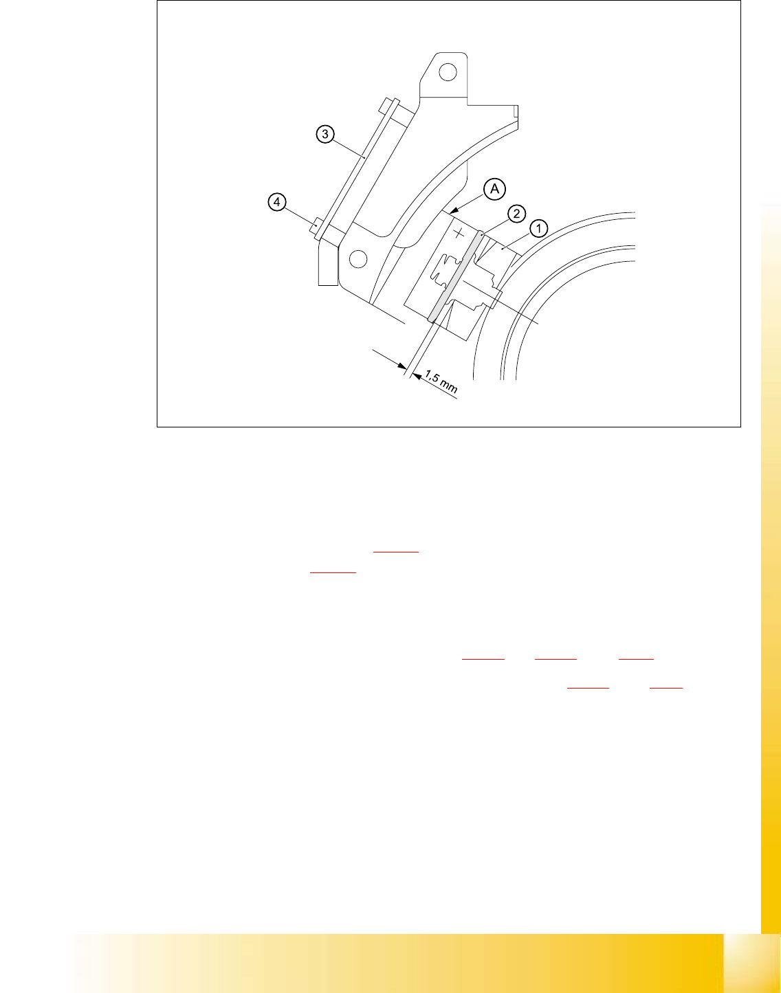
Fig. 5.4 - 23 Setting the distance between the rotary encoder window and the incremental disk
of the sleeve to 1.5 mm
– Remove the gauge for the star.
– Remove the sleeve from the star.
– Fix the RSF board (item 3 in Fig. 5.4 - 23
) in place using the two M2.5x4 hexagon socket-head
screws (item 4 in Fig. 5.4 - 23
).
– Connect the plug connector to socket X7 on the intermediate terminal block.
– Place the black blanking cap over the RSF board.
– Fit and adjust the star as described in sections 5.4.5.4
and 5.4.5.5, page 5 - 44 onwards.
– Fit the front part of the collect&place head as described in section 5.4.3.3
, page 5 - 39 onwards.
5.4.10.5 Adjustments
➠ Use the SITEST program to check that the rotary encoder is working correctly.