HS50_advance_level 1_20200522_221201 (1).pdf - 第162页
06/2002 E dition Studen t Guide H S-50 Advance d I 5 DLM1 C&P H ead 70 5 Fig . 5.4 - 2 6 Colle ct&pl ace head - comp ress ed air co nnec tion s (1) Compres s ed a ir conne ction of the forced ai r unit (2) 3 comp…
Student Guide HS-50 Advanced I 06/2002 Edition
5 DLM1 C&P Head
69
5.4.12 Removal of rear part of head
5.4.12.1 Tools and equipment
– Set of DIN 911 Allen keys
– Setting instructions
– SITEST program
5.4.12.2 Parts
Collect&place head SP 12 complete / DLM1, item no. 00335700-01 5
5.4.12.3 Dismantling the collect&place head
– Switch the placement system off and secure it to prevent switching on again as described in
section 5.4.1
, page - 32.
– Detach the plug-in connections on the head board 00331451-xx (see Fig. 5.4 - 25
).
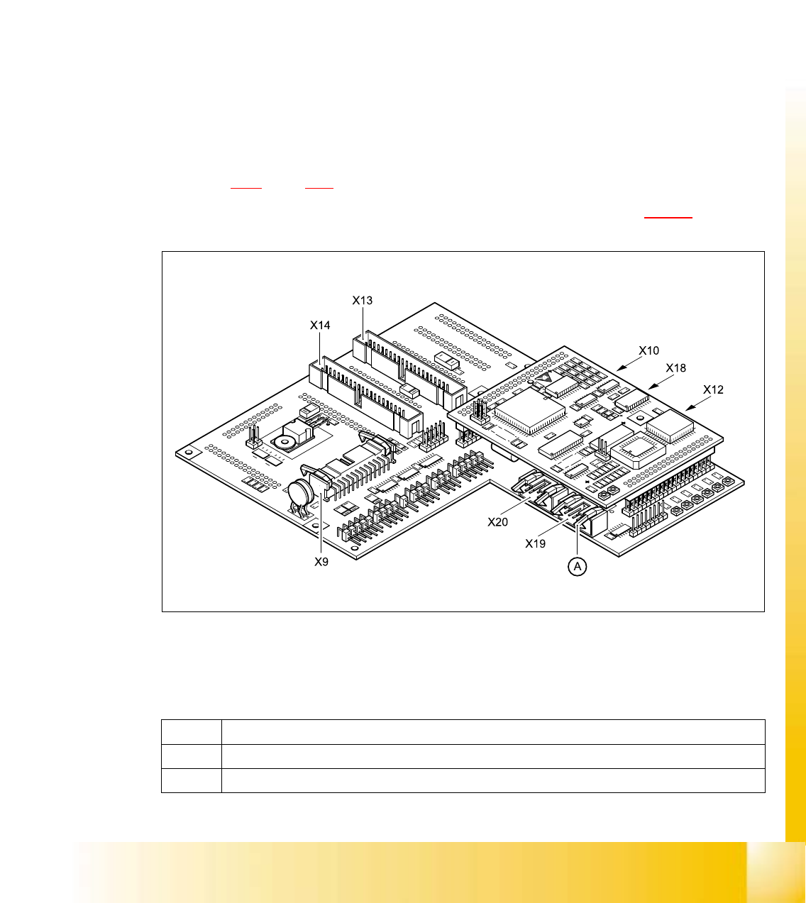
Fig. 5.4 - 25 Head board - plug-in connections
(A) Lift both locking levers at the same time and the plug will be pushed out.
X9 For the component illumination controller and component camera
X10 For the vacuum measuring board
Tab. 5.4 - 3 Plug-in connections on the head board
06/2002 Edition Student Guide HS-50 Advanced I
5 DLM1 C&P Head
70
5
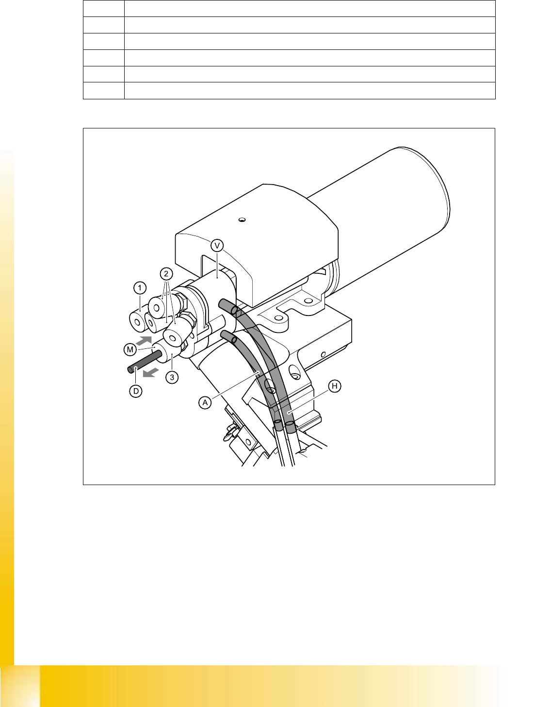
Fig. 5.4 - 26 Collect&place head - compressed air connections
(1) Compressed air connection of the forced air unit
(2) 3 compressed air connections for the holding circuit
(3) Compressed air connection for the placement circuit
A Hose connection to placement circuit 5
H Hose connection to holding circuit 5
X12 For the DP-axis, motor and tacho
X13 For plug X2 on the intermediate distribution board
X14 For plug X1 on the intermediate distribution board
X18 For the infeed motor of the DP-axis
X19 For the "Placement circuit" valve positioning drive (star station 1)
X20 For the "Reject circuit" valve positioning drive (star station 3)
Tab. 5.4 - 3 Plug-in connections on the head board
Student Guide HS-50 Advanced I 06/2002 Edition
5 DLM1 C&P Head
71
PLEASE NOTE:
Refer to Fig. 5.4 - 29
on page 5 - 73 and Table 5.4 - 5 on page 5 - 74 for connecting the
compressed air hoses.
➠ Push the collar (3) towards the vacuum generator (V) and remove the black compressed air
hose (D).
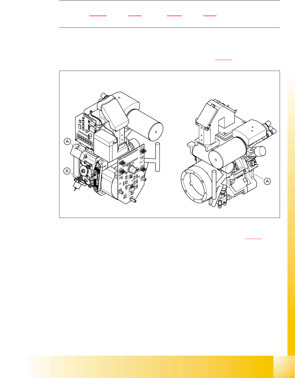
➠ Undo the three hexagon socket-head screws (M4x16) (item A in 5.4 - 27).
5
Fig. 5.4 - 27 Fixing the collect&place head on the head mount
➠ Carefully pull the collect&place head away from the parallel pins (Item 4 in Fig. 5.4 - 28) on the
head mount and remove it from the placement system.