HS50_advance_level 1_20200522_221201 (1).pdf - 第165页
Studen t Guide HS-50 A dvanced I 06/200 2 Edition 5 DLM1 C&P Head 73 ➠ Chec k that the plugs of the 40-pin ribbon cables between the intermedi at e distribution board and h ead board are c orrectly assign ed: ➠ Make …
06/2002 Edition Student Guide HS-50 Advanced I
5 DLM1 C&P Head
72
5.4.12.4 Fitting the collect&place head on the head mount
5
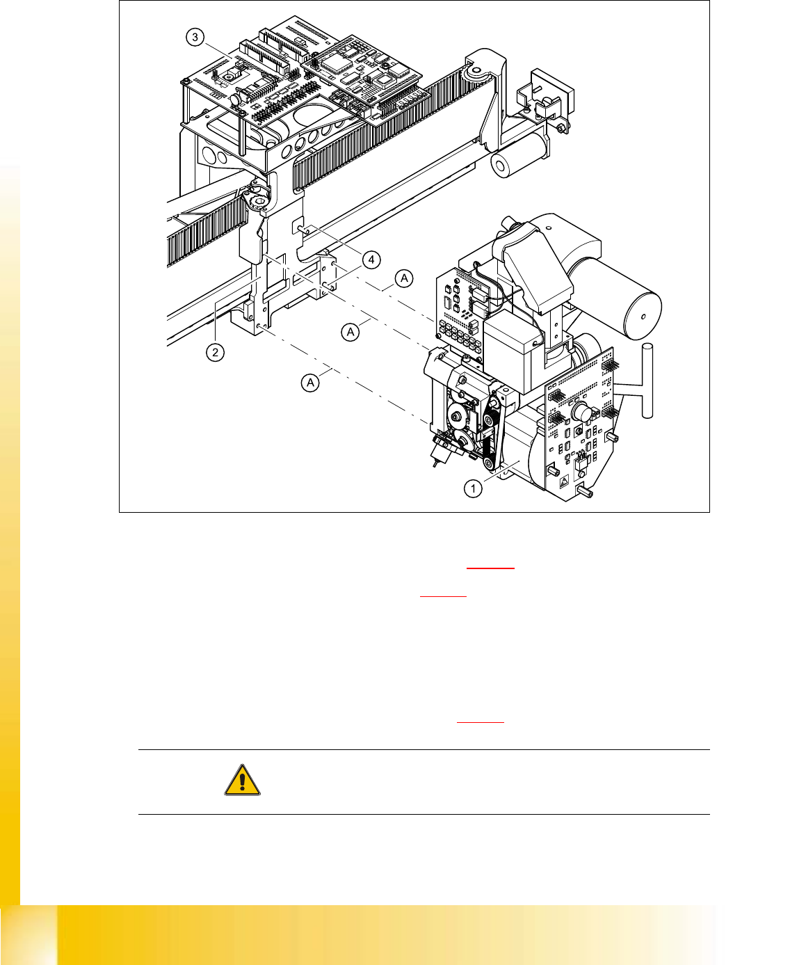
Fig. 5.4 - 28 Fitting the collect&place head
➠ Carefully move the collect&place head (item 1 in Fig. 5.4 - 28) onto the head mount (2).
➠ Make sure that the parallel pins (item 4 in Fig. 5.4 - 28) on the head mount slide into the holes
in the back part of the collect&place head.
➠ Carefully push the collect&place head towards the head mount until it is lying flat.
➠ Use three M4x16 hexagon socket-head screws to fix the collect&place head (A).
➠ Connect the plugs for the collect&place head to the head board.
The plug positions and assignment is shown in Fig. 5.4 - 25
.
CAUTION Check the polarity of the plugs before connecting. 5
➠ Make sure that the plugs are firmly locked in place.
Student Guide HS-50 Advanced I 06/2002 Edition
5 DLM1 C&P Head
73
➠ Check that the plugs of the 40-pin ribbon cables between the intermediate distribution board
and head board are correctly assigned:
➠ Make sure that the cables are not damaged and that there is no strain on the connecting
cables.
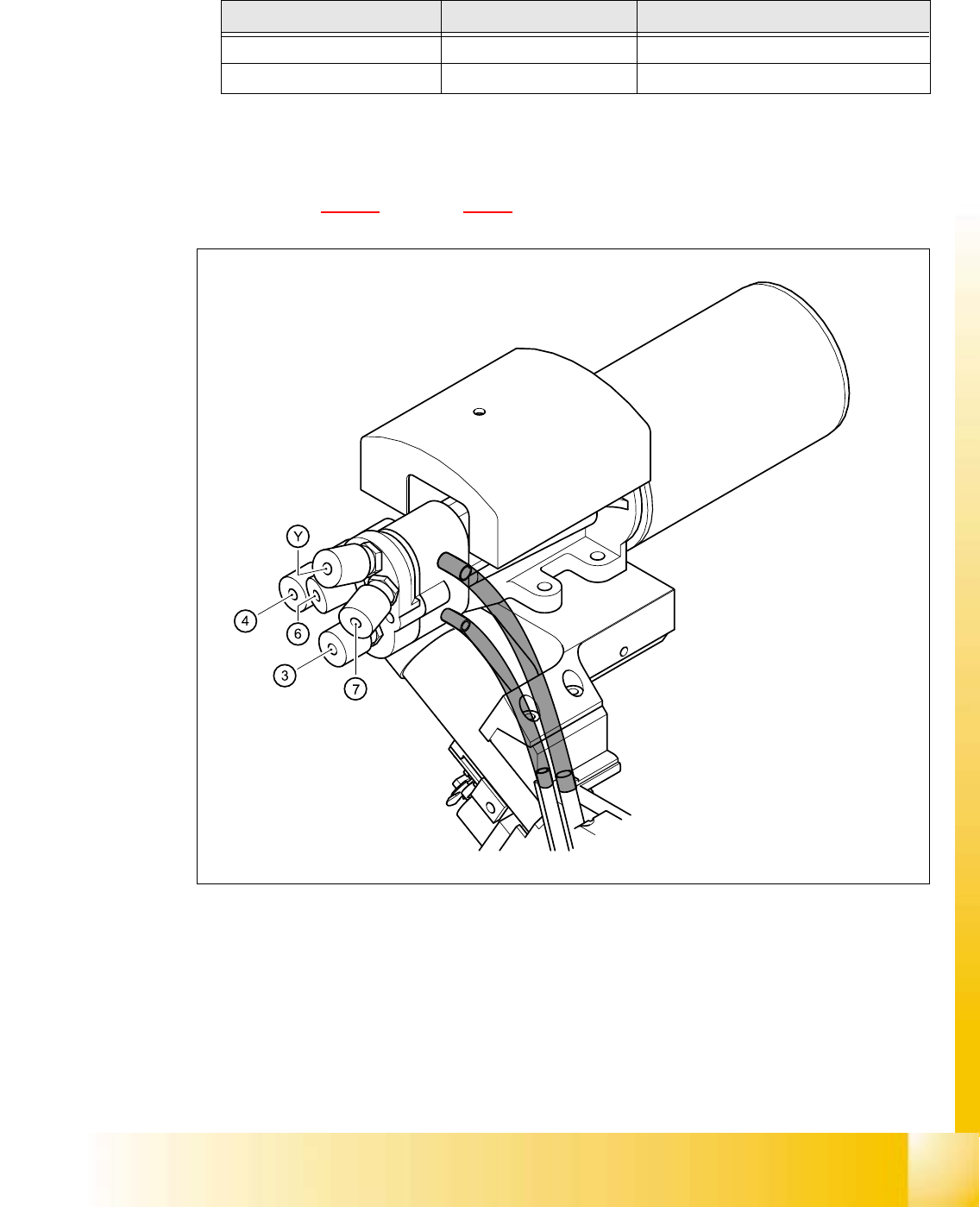
➠ Refer to Fig. 5.4 - 29 and Table 5.4 - 5 for connecting the compressed air hoses.
5
Fig. 5.4 - 29 Connection diagram for the compressed air hoses on the collect&place head
Cable Head board Intermediate distribution board
00333491-W1 X14 X1
00333491-W2 X13 X2
Tab. 5.4 - 4 Plug-in connections for the flat ribbon cables on the head board
06/2002 Edition Student Guide HS-50 Advanced I
5 DLM1 C&P Head
74
5
5
5.4.12.5 Settings
➠ Close the protective cover.
➠ Check that you have removed all tools and equipment from inside the placement system.
➠ Start the placement system.
➠ Use the SITEST program to calibrate the collect&place head.
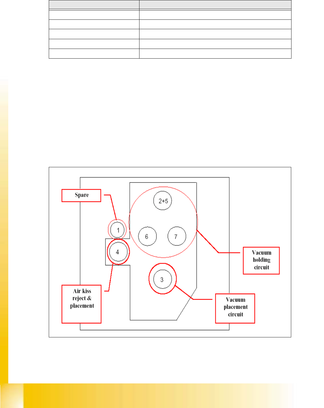
Fig. 5.4 - 30 Connection positions for vacuum generator on DLM1-12 head for machines HS50 and HS55
Compressed air hose no. Connection
1 Not connected
2 + 5 Via Y-shaped connecting piece to holding circuit (Y)
3 Placement circuit
4 Forced air unit
6 + 7 Holding circuit
Tab. 5.4 - 5 Connection diagram for the compressed air hoses on the collect&place head