HS50_advance_level 1_20200522_221201 (1).pdf - 第167页
Studen t Guide HS-50 A dvanced I 06/200 2 Edition 5 DLM1 C&P Head 75 5.4. 13 Removal o f DP st at ion 5.4. 13.1 T ools and equipment – Set of DIN 91 1 Allen keys – SITES T program 5. 4.13 .2 Pa rt s T urning station …
06/2002 Edition Student Guide HS-50 Advanced I
5 DLM1 C&P Head
74
5
5
5.4.12.5 Settings
➠ Close the protective cover.
➠ Check that you have removed all tools and equipment from inside the placement system.
➠ Start the placement system.
➠ Use the SITEST program to calibrate the collect&place head.
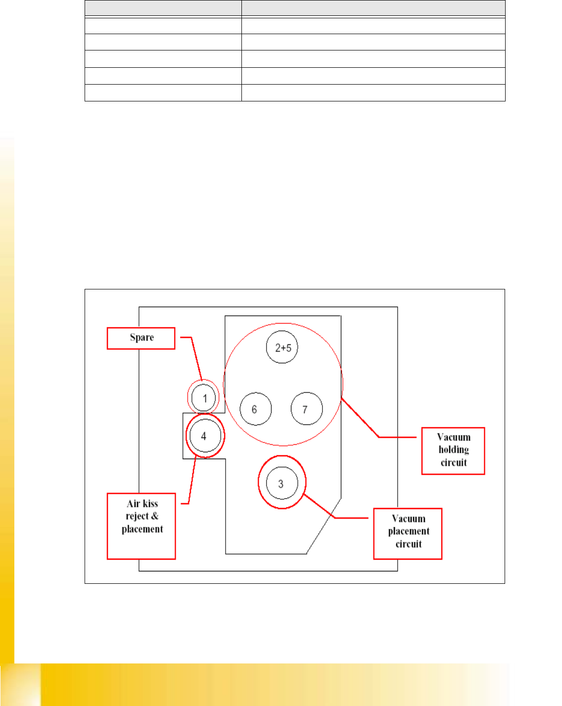
Fig. 5.4 - 30 Connection positions for vacuum generator on DLM1-12 head for machines HS50 and HS55
Compressed air hose no. Connection
1 Not connected
2 + 5 Via Y-shaped connecting piece to holding circuit (Y)
3 Placement circuit
4 Forced air unit
6 + 7 Holding circuit
Tab. 5.4 - 5 Connection diagram for the compressed air hoses on the collect&place head
Student Guide HS-50 Advanced I 06/2002 Edition
5 DLM1 C&P Head
75
5.4.13 Removal of DP station
5.4.13.1 Tools and equipment
– Set of DIN 911 Allen keys
– SITEST program
5.4.13.2 Parts
Turning station / DLM1, item no. 00341780-01 5
5.4.13.3 Dismantling the DP station
➠ Switch the placement system off and secure it to prevent switching on again as described in
section 5.4.1
, page - 32.
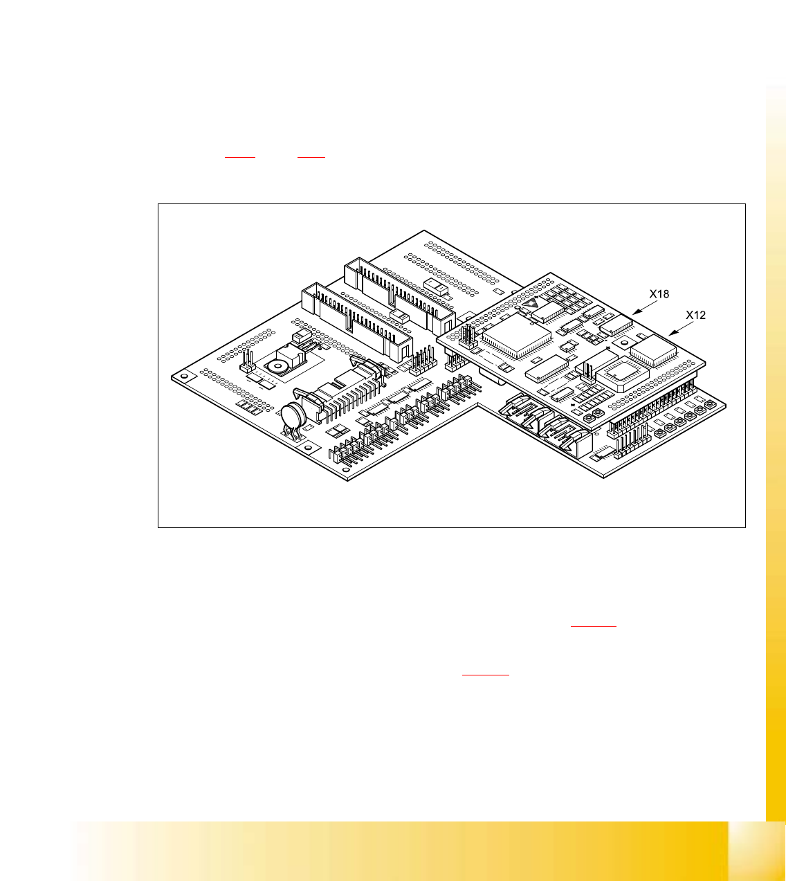
➠ Remove the plugs from sockets X12 and X18 on the head board.
5
Fig. 5.4 - 31 Plug-in connections of the turning station on the head board
➠ Push the collect&place head until it reaches the stopper on the deflection roller of the X-axis
toothed belt.
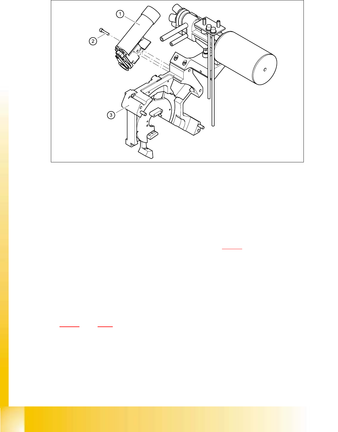
➠ Undo the M3x25 hexagon socket-head screw (see item 2 in Fig. 5.4 - 32) on the rear panel of
the back part.
➠ Carefully pull the turning station (item 1 in Fig. 5.4 - 32) back and remove.
06/2002 Edition Student Guide HS-50 Advanced I
5 DLM1 C&P Head
76
5
Fig. 5.4 - 32 Turning station / DLM1
(1) Turning station / DLM1
(2) M3x25 hexagon socket-head screw
(3) Back part of the collect&place head
5.4.13.4 Fitting the DP station
➠ Make sure that the contact surfaces of the turning station and rear panel are clean.
➠ Insert the M3 x 25 hexagon socket-head screw (item 2 in Fig. 5.4 - 31) into the hole in the
centering station.
➠ Run the cable between the vacuum hose and the vacuum generation socket.
➠ Place the holes in the turning station on the parallel pins.
➠ Carefully push the turning station towards the back part until it reaches the stop.
➠ Fix the turning station with the hexagon socket-head screw.
➠ Plug the cable into sockets X12 and X18 on the head board (see item X12 and X18 in Fig.
5.4 - 31
, page 5 - 75.
5.4.13.5 Settings
➠ Switch the placement system on and start it up.
➠ Use the SITEST program to run a function test.