HS50_advance_level 1_20200522_221201 (1).pdf - 第171页
Studen t Guide HS-50 A dvanced I 06/200 2 Edition 5 DLM1 C&P Head 79 CAUTION 5 Check that the ribbon cab les (item 1 an d 2 in Fig. 5.4 - 1 1 ) are laid c o rr ectly . The ribbon cabl e (item 2 in Fi g. 5. 4 - 1 1 ) …
06/2002 Edition Student Guide HS-50 Advanced I
5 DLM1 C&P Head
78
5
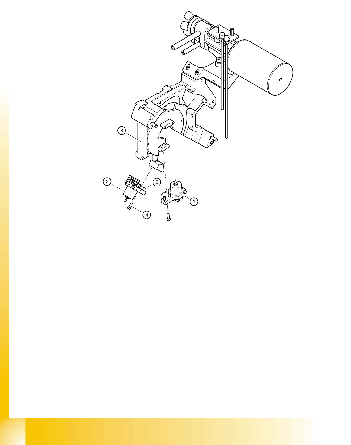
Fig. 5.4 - 33 Replacing the valve positioning drive
(1) "Placement circuit" valve positioning drive
(2) "Reject circuit" valve positioning drive
(3) Back part of the collect&place head
(4) M3x10 hexagon socket-head screw
(5) Parallel pins, 2 x per drive
5
5.4.14.4 Fitting the valve positioning drive
➠ Insert the valve positioning drive, making sure that it is seated correctly on the parallel pins.
➠ Loosely tighten the hexagon socket-head screw.
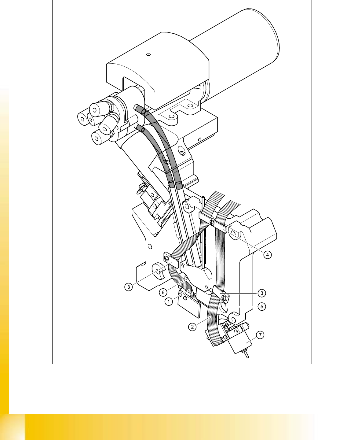
➠ Use the cable clamp assemblies (items 2, 3, and 4 in Fig. 5.4 - 11) to fix the ribbon cables in
position, ensuring that the ribbon cables are not squashed.

Student Guide HS-50 Advanced I 06/2002 Edition
5 DLM1 C&P Head
79
CAUTION 5
Check that the ribbon cables (item 1 and 2 in Fig. 5.4 - 11
) are laid correctly. The ribbon cable
(item 2 in Fig. 5.4 - 11
) from the valve adjustment unit to the reject station (item 6 in Fig. 5.4
- 11) must run outside the hole (item 5 in Fig. 5.4 - 11), otherwise it will be damaged when the
collect&place head is fitted on the head mount. 5
5
5
5
5
5
5
5
5
5
5
Key to Fig. 5.4 - 11
(1) Flat ribbon cable for the ’Placement’ valve adjustment unit
(2) Flat ribbon cable for the ’Reject circuit’ valve adjustment unit
(3) Cable clamp assembly
(4) Cable clamp assembly
(5) Hole
(6) ’Placement’ valve positioning drive
(7) ’Reject circuit’ valve positioning drive
5
06/2002 Edition Student Guide HS-50 Advanced I
5 DLM1 C&P Head
80
5
Fig. 5.4 - 34 Laying the ribbon cables for the valve adjustment drives