HS50_advance_level 1_20200522_221201 (1).pdf - 第174页
06/2002 E dition Studen t Guide H S-50 Advance d I 5 DLM1 C&P H ead 82 5. 4.14 .6 Set ti ngs ➠ Use the SITEST program to test that the valve positioning drive is f unction ing corr ectly . ➠ Use the SITEST program to…
Student Guide HS-50 Advanced I 06/2002 Edition
5 DLM1 C&P Head
81
5.4.14.5 Mechanical adjustment
5
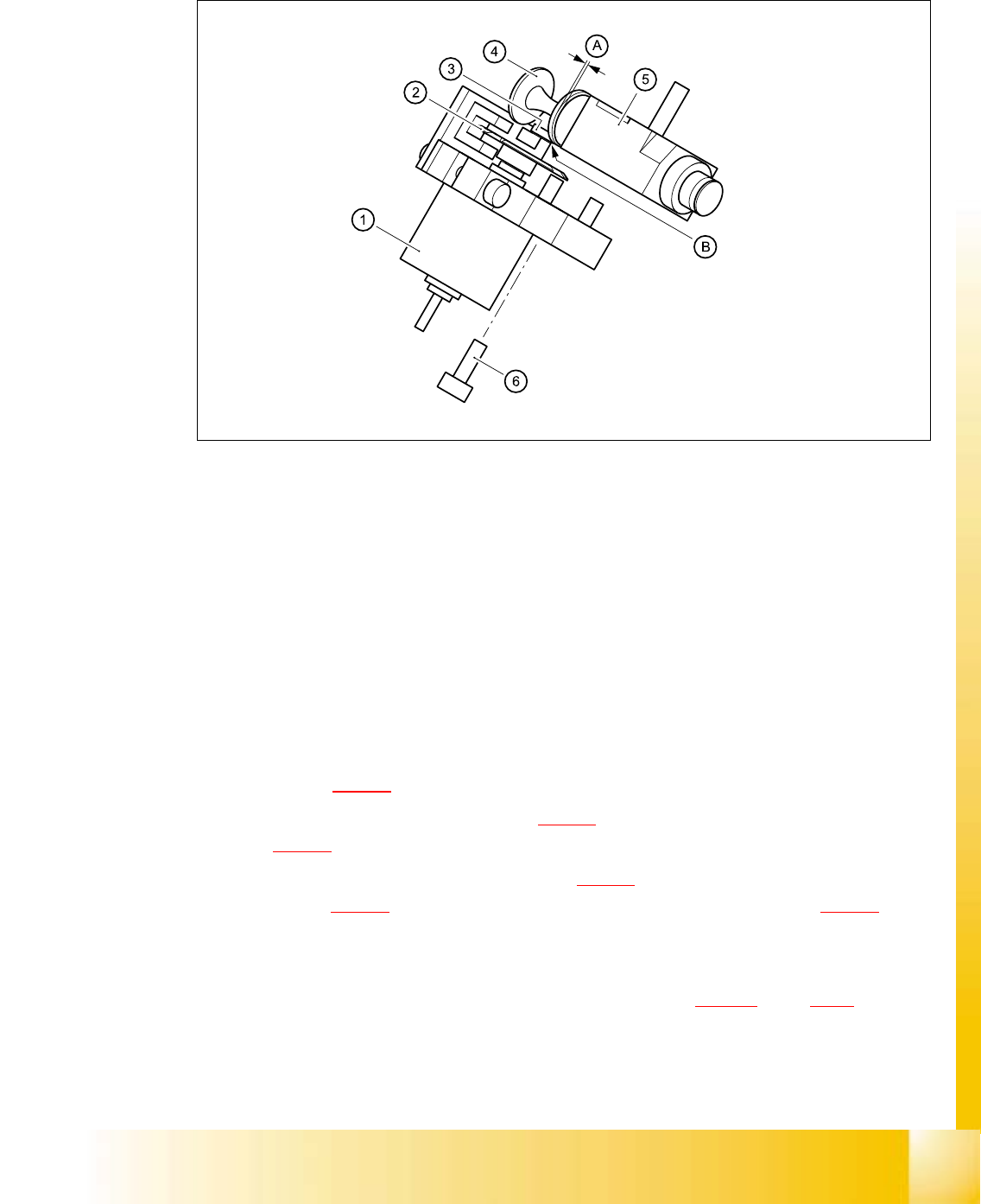
Fig. 5.4 - 35 Mechanical adjustment of the valve positioning drives
(1) Stepping motor
(2) Adjusting disk
(3) Deep-groove ball bearings
(4) Valve plunger
(5) Valve casing
(6) M3x10 hexagon socket-head screw
(7) Valve positioning drive (flange)
5
➠ Use the feeler gauge to set the distance between the valve plunger and valve casing to 0.2 mm
(item A in Fig. 5.4 - 12
).
➠ Turn the adjusting disk (see item 2 in Fig. 5.4 - 12) until the deep-groove ball bearings (item 3
in Fig. 5.4 - 12
) point towards the valve casing.
➠ Move the valve positioning drive (item 7 in Fig. 5.4 - 12) so that the deep-groove ball bearings
(item 3 in Fig. 5.4 - 12
) come into contact with the valve plunger (item 4 in Fig. 5.4 - 12) at
position B.
➠ Use the hexagon socket-head screw (item 6) to fix valve adjustment unit in this position.
➠ Attach the collect&place head to the head mount (see section 5.4.12.4, page 5 - 72).

06/2002 Edition Student Guide HS-50 Advanced I
5 DLM1 C&P Head
82
5.4.14.6 Settings
➠ Use the SITEST program to test that the valve positioning drive is functioning correctly.
➠ Use the SITEST program to calibrate the collect&place head.
Student Guide HS-50 Advanced I 06/2002 Edition
5 DLM1 C&P Head
83
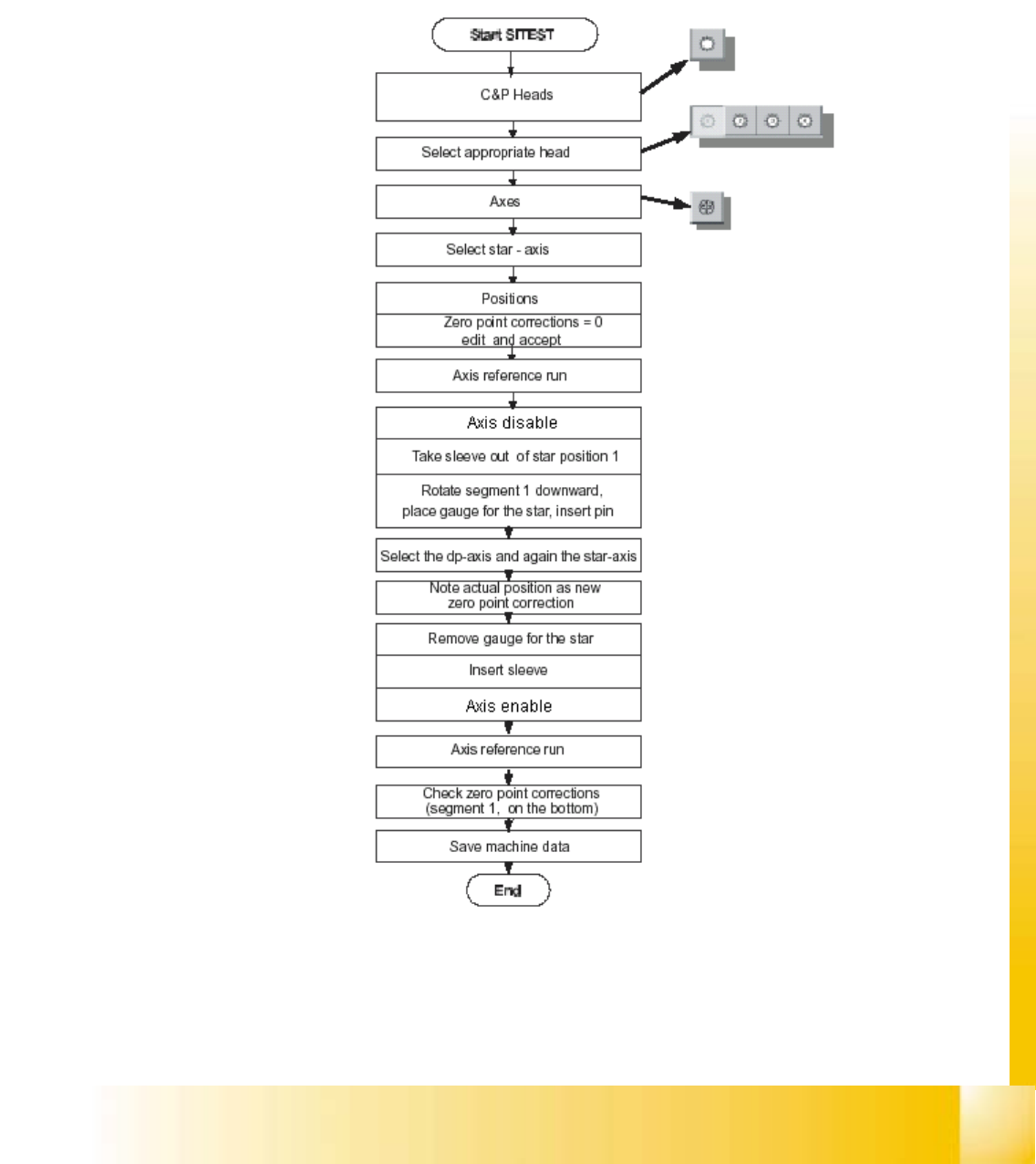
5.5 Adjustment
5.5.1 Determination of Zero Point Correction Star - Axis Collect & Place Head
fig 5.5 - 1 Flow chart of zero point corrections