HS50_advance_level 1_20200522_221201 (1).pdf - 第175页
Studen t Guide HS-50 A dvanced I 06/200 2 Edition 5 DLM1 C&P Head 83 5.5 Adjust ment 5.5. 1 Determ in at ion of Zer o Point Correctio n S ta r - Axis Co llect & P lace Head f ig 5.5 - 1 F low cha rt o f z er o po…

06/2002 Edition Student Guide HS-50 Advanced I
5 DLM1 C&P Head
82
5.4.14.6 Settings
➠ Use the SITEST program to test that the valve positioning drive is functioning correctly.
➠ Use the SITEST program to calibrate the collect&place head.
Student Guide HS-50 Advanced I 06/2002 Edition
5 DLM1 C&P Head
83
5.5 Adjustment
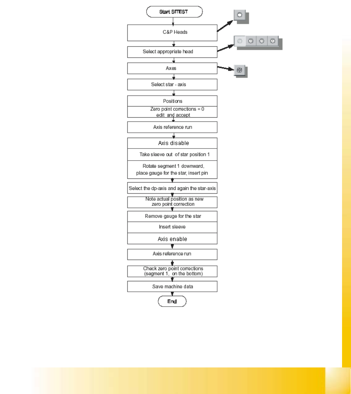
5.5.1 Determination of Zero Point Correction Star - Axis Collect & Place Head
fig 5.5 - 1 Flow chart of zero point corrections
06/2002 Edition Student Guide HS-50 Advanced I
5 DLM1 C&P Head
84
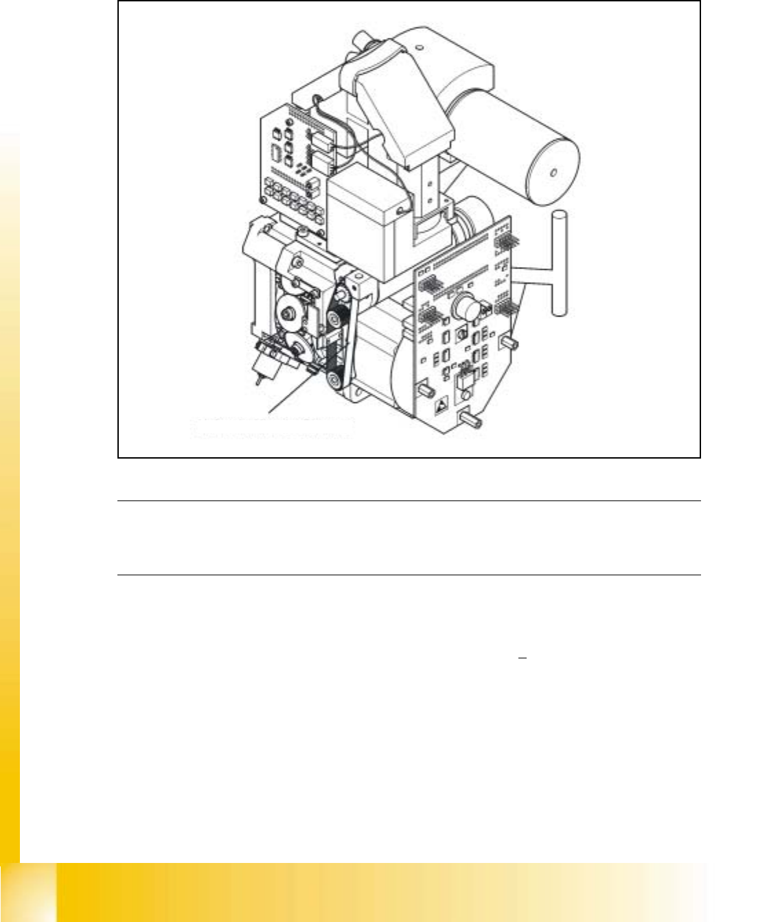
5.5.2 Belt Tension of the Z-Axis
➠ Attach the measuring head in front of the toothed belt.
fig 5.5 - 2 Measuring point for the belt tension of the z-axis
NOTE
The measuring point of the measuring pin must be in the middle of the two deflection pulleys.
The measuring pin should be at a maximum distance of 2 - 3 mm, from the toothed belt. 5
➠ Strike the toothed belt, to reach a stimulation of vibration of the open ended toothed belt.
➠ Stretch the belt over the fastening of the driving motor (compare: service manual) if the
frequency of the belt tension does not reach a value of 280 Hz +
10 Hz.
➠ Repeat these instructions until the belt tension is correct.
Messpunkt: Riemenmitte /
measuring point: middle of belt