HS50_advance_level 1_20200522_221201 (1).pdf - 第179页
Studen t Guide HS-50 A dvanced I 06/200 2 Edition 5 DLM1 C&P Head 87 ➠ Adj us t to the val ues of the table b elow: NOTE Both forced air circuits are c ontrolled by a s ingle valve and therefore are mutually dependen…
06/2002 Edition Student Guide HS-50 Advanced I
5 DLM1 C&P Head
86
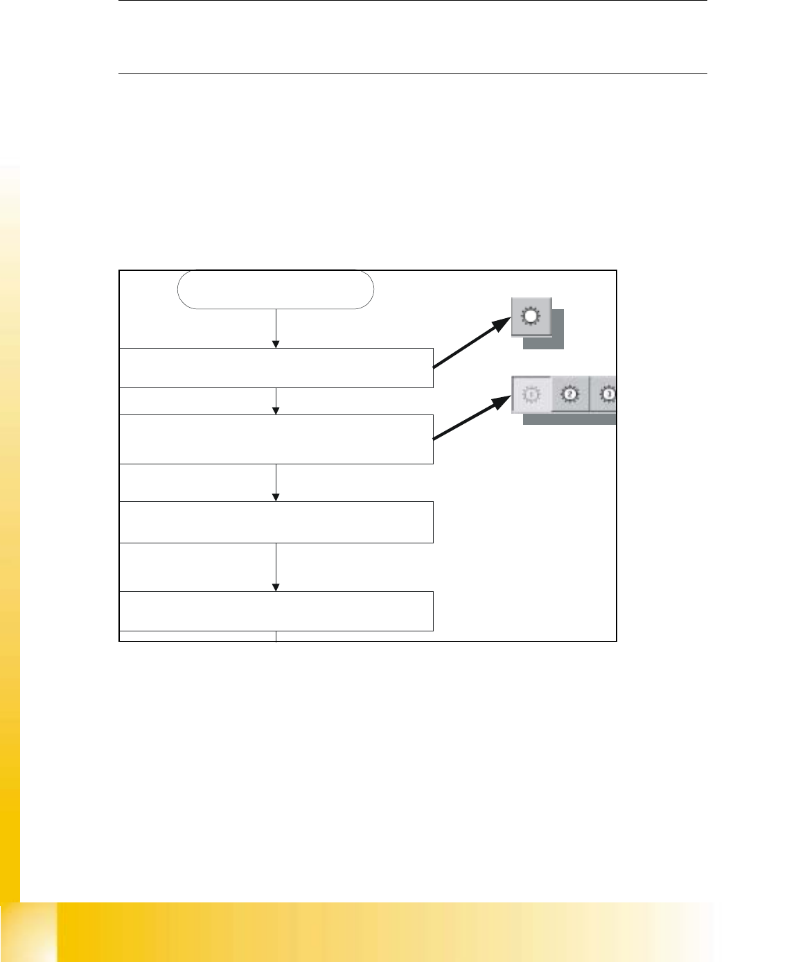
5.5.3.3 Adjustments of the Air Pressure Values with the Help of a Compressed Air Testing
Device
fig 5.5 - 4 Flow chart determining air pressure values
NOTE
Air pressure values, displayed on the screen of the station computer, under option "Measure air
pressure" of the "Single functions", or in the SITEST program, do not correspond to the air
pressure values actually set at the nozzles.
They solely serve to check that the forced air valve is functioning correctly.
Therefore, the air pressure may not be adjusted with the values displayed on the screen.
Instead, use only the values determined with the compressed air testing device. 5
4
1
2
3

Student Guide HS-50 Advanced I 06/2002 Edition
5 DLM1 C&P Head
87
➠ Adjust to the values of the table below:
NOTE
Both forced air circuits are controlled by a single valve and therefore are mutually dependent.
Using two different restrictor valves (compare item 3 and 4 in Fig. 5.1.10), it is however possible,
to adjust differing pressure values for each circuit. 5
➠ Repeat these adjustments several times, as the pick - up / placement circuit are mutually
dependent.
NOTE
Make sure that the test sensor tube is attached air - tight on the nozzle. 5
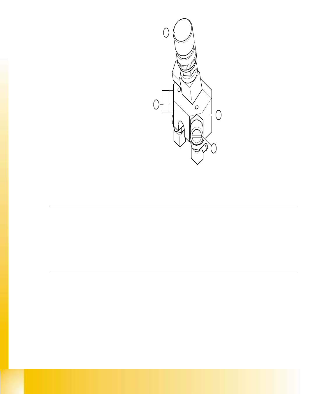
5.5.4 RSF Digital Rotary Transducer of DP - Axis
5.5.5 RSF Digital Transducer of DP - Axis
➠ Remove sleeve 1 and insert the star zero point gauge, in order to mechanically fix the star.
➠ Now, remove sleeve 4 as well and align the transducer.
➠ With the help of a parallel pin, set the digital transducer of the dp - axis to 1.5 mm, parallel to
the glass pane of the segment.
NOTE
A parallel pin of 1.4 mm must easily fit through the gap, a parallel pin of 1.6 mm must be too big
to fit. 5
Forced Air Values
Adjustment with Compressed Air
Testing Device
Measurement taken on Nozzle
Displayed on the Monitor:
(Only in Pick - Up and Placement
Circuit)
pick - up / placement
circuit 150 mbar (100 - 200 mbar) e.g.: 250 mbar
reject circuit 250 mbar (200 - 300 mbar) reject cicuit does not have a sensor
06/2002 Edition Student Guide HS-50 Advanced I
5 DLM1 C&P Head
88
5.5.6 Light Barrier, Bottom Position
NOTE
In order to adjust the light barrier, use a parallel pin and adjust it to a distance of 1.33 mm to the
sleeve. 5
5.5.7 Adjustment of Mechanical Position of Valve Drives
➠ Set the motor position of the valve drives "Pick-up / Placement" and "Ejection" according to the
figure below.
➠ Insert the distance gauge (0,2mm) between valve plunger and valve casing.
➠ Turn the valve drive to 90° degrees, opposite to its initial position.
5
fig 5.5 - 5 Position of valve drives
5.5.8 Other Mechanical Adjustments on the Star
➠ Insert the blast air transition tubes so that they will protrude 0.5 mm from the surface of the
circular arc guide.
Blasluft "EIN"
Bestück- und Abholkreis
Entsprechenden Kopf wählen
C&P Köpfe
SITEST starten