HS50_advance_level 1_20200522_221201 (1).pdf - 第180页
06/2002 E dition Studen t Guide H S-50 Advance d I 5 DLM1 C&P H ead 88 5.5.6 Light Bar rier , Bo ttom P o sitio n NOTE In order to adjust the li gh t barri er , use a paral lel pin and adjust it t o a distance of 1.3…

Student Guide HS-50 Advanced I 06/2002 Edition
5 DLM1 C&P Head
87
➠ Adjust to the values of the table below:
NOTE
Both forced air circuits are controlled by a single valve and therefore are mutually dependent.
Using two different restrictor valves (compare item 3 and 4 in Fig. 5.1.10), it is however possible,
to adjust differing pressure values for each circuit. 5
➠ Repeat these adjustments several times, as the pick - up / placement circuit are mutually
dependent.
NOTE
Make sure that the test sensor tube is attached air - tight on the nozzle. 5
5.5.4 RSF Digital Rotary Transducer of DP - Axis
5.5.5 RSF Digital Transducer of DP - Axis
➠ Remove sleeve 1 and insert the star zero point gauge, in order to mechanically fix the star.
➠ Now, remove sleeve 4 as well and align the transducer.
➠ With the help of a parallel pin, set the digital transducer of the dp - axis to 1.5 mm, parallel to
the glass pane of the segment.
NOTE
A parallel pin of 1.4 mm must easily fit through the gap, a parallel pin of 1.6 mm must be too big
to fit. 5
Forced Air Values
Adjustment with Compressed Air
Testing Device
Measurement taken on Nozzle
Displayed on the Monitor:
(Only in Pick - Up and Placement
Circuit)
pick - up / placement
circuit 150 mbar (100 - 200 mbar) e.g.: 250 mbar
reject circuit 250 mbar (200 - 300 mbar) reject cicuit does not have a sensor
06/2002 Edition Student Guide HS-50 Advanced I
5 DLM1 C&P Head
88
5.5.6 Light Barrier, Bottom Position
NOTE
In order to adjust the light barrier, use a parallel pin and adjust it to a distance of 1.33 mm to the
sleeve. 5
5.5.7 Adjustment of Mechanical Position of Valve Drives
➠ Set the motor position of the valve drives "Pick-up / Placement" and "Ejection" according to the
figure below.
➠ Insert the distance gauge (0,2mm) between valve plunger and valve casing.
➠ Turn the valve drive to 90° degrees, opposite to its initial position.
5
fig 5.5 - 5 Position of valve drives
5.5.8 Other Mechanical Adjustments on the Star
➠ Insert the blast air transition tubes so that they will protrude 0.5 mm from the surface of the
circular arc guide.
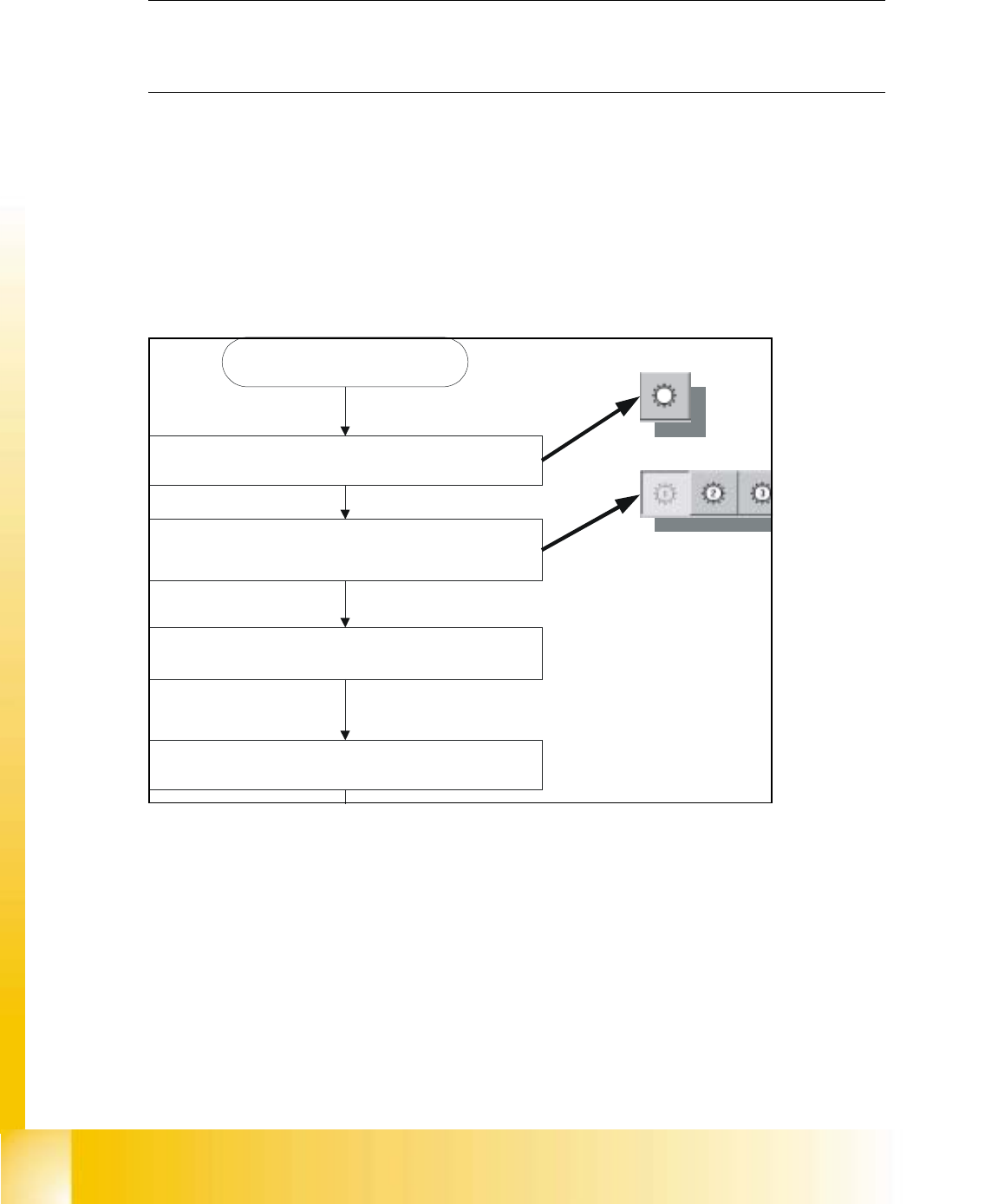
Blasluft "EIN"
Bestück- und Abholkreis
Entsprechenden Kopf wählen
C&P Köpfe
SITEST starten

6 Operating the SITEST
Software