HS50_advance_level 1_20200522_221201 (1).pdf - 第181页
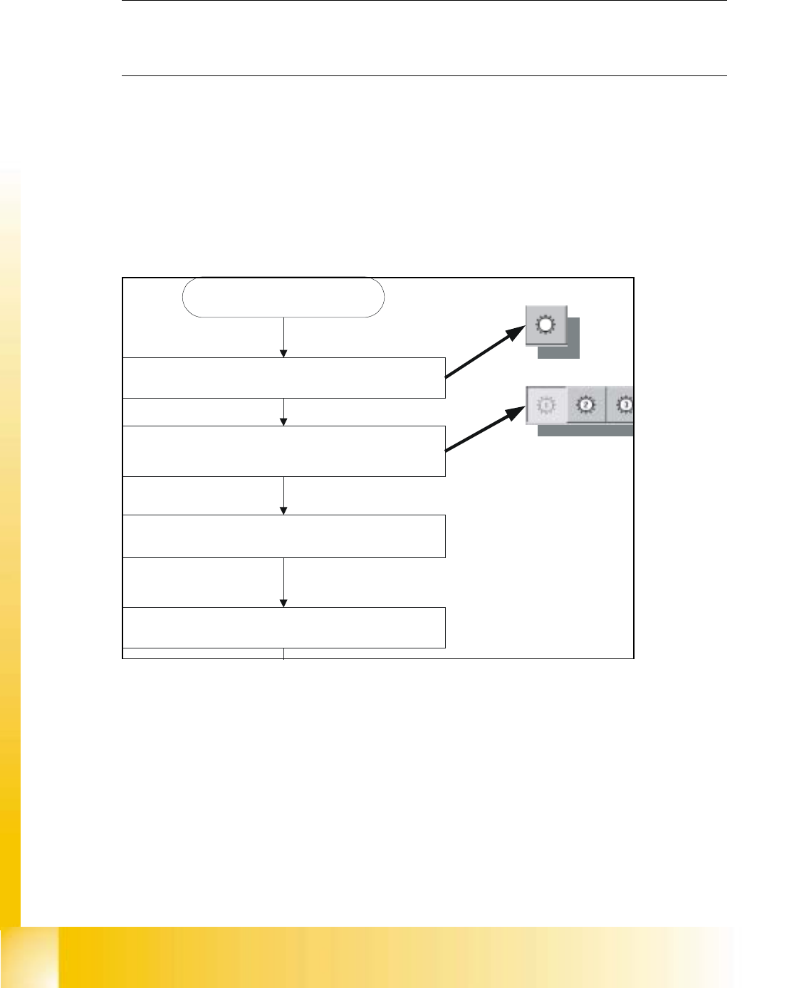
6 Operatin g the SITEST Sof tware
06/2002 Edition Student Guide HS-50 Advanced I
5 DLM1 C&P Head
88
5.5.6 Light Barrier, Bottom Position
NOTE
In order to adjust the light barrier, use a parallel pin and adjust it to a distance of 1.33 mm to the
sleeve. 5
5.5.7 Adjustment of Mechanical Position of Valve Drives
➠ Set the motor position of the valve drives "Pick-up / Placement" and "Ejection" according to the
figure below.
➠ Insert the distance gauge (0,2mm) between valve plunger and valve casing.
➠ Turn the valve drive to 90° degrees, opposite to its initial position.
5
fig 5.5 - 5 Position of valve drives
5.5.8 Other Mechanical Adjustments on the Star
➠ Insert the blast air transition tubes so that they will protrude 0.5 mm from the surface of the
circular arc guide.
Blasluft "EIN"
Bestück- und Abholkreis
Entsprechenden Kopf wählen
C&P Köpfe
SITEST starten
6 Operating the SITEST
Software