HS50_advance_level 1_20200522_221201 (1).pdf - 第192页
06/2002 E dition Studen t Guide H S-50 Advance d I 6 Operati ng the S IT ES T Softwa r e 8 6.3.4 M ai n V iew - Menu Bar : Mode and V iew SIPLAC E HS -50 / HS-55 6 Shut s the st ation c omput er down complete ly w it hin…
Student Guide HS-50 Advanced I 06/2002 Edition
6 Operating the SITEST Software
7
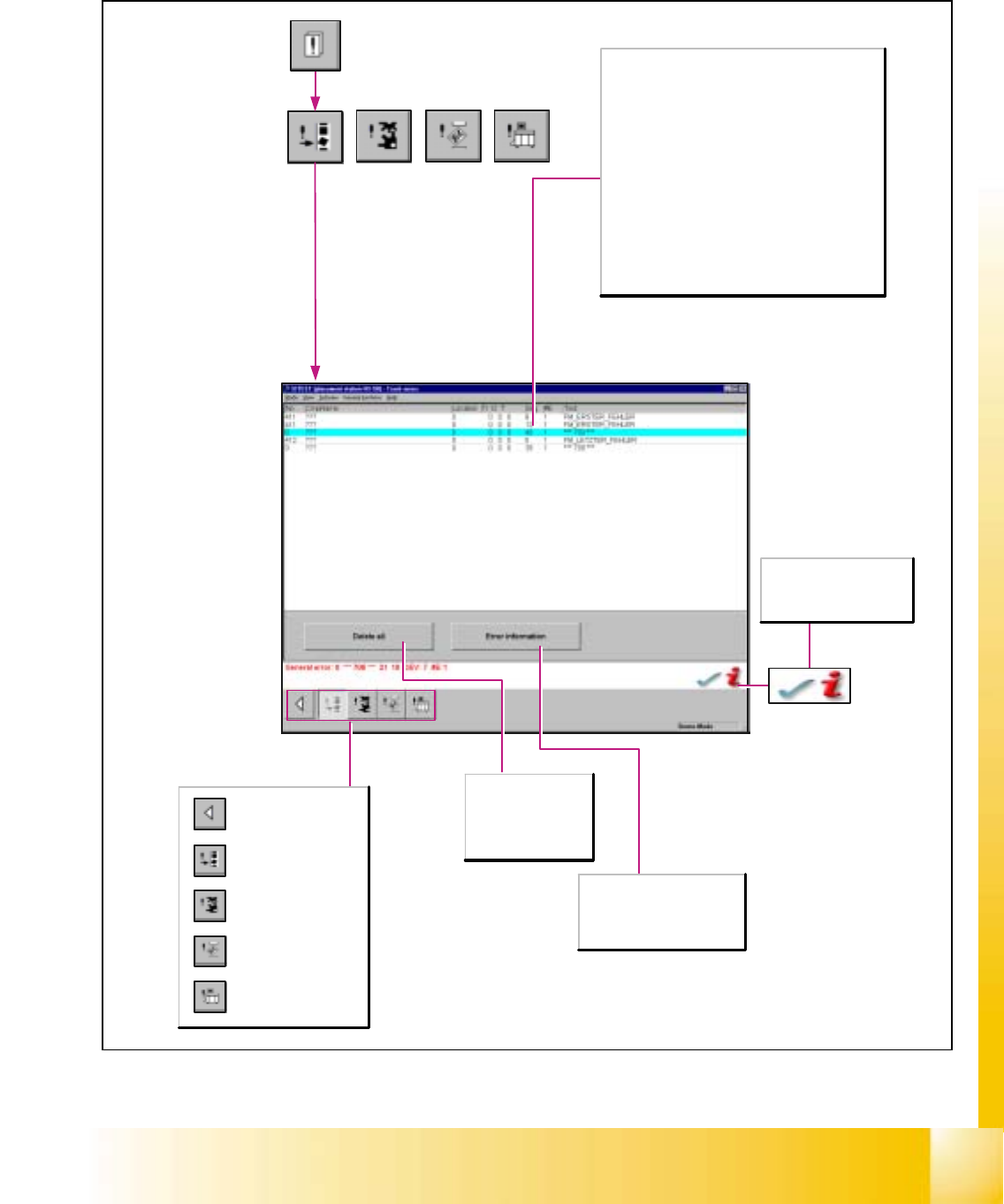
6.3.3 Display Errors
6
Key to the table:
No.
Indicates the error numbers of the individual errors.
Info1, Info2
Only for Siemens-internal use.
DEV
Indicates the applicable pick-up side, i.e. the gantry on
which the error has occurred.
#E
Indicates how often the particular error has already
occurred.
Text
Describes the error at issue.
Delete all
Deletes all error
messages of the
error class currently
displayed.
After the successful
completion of
troubleshooting activities,
the current error is deleted.
Error information
Starts a help system listing the
possible causes of selected
errors and displays possible
corrective actions to be taken.
Call-up of the display
of the general errors.
Call-up of the transport
error display.
Call-up of the machine
error display.
Call-up of the track
error display.
Return to the main
view.
06/2002 Edition Student Guide HS-50 Advanced I
6 Operating the SITEST Software
8
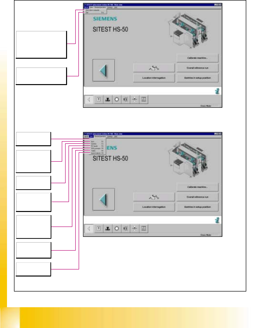
6.3.4 Main View - Menu Bar: Mode and View SIPLACE HS-50 / HS-55
6
Shuts the station computer
down completely within a few
seconds. All active programs
are aborted.
Subsequently, the computer
may be switched off.
Esc
Aborts the processing and the
SITEST test program is exited.
F1
Return to the main
view.
F2
Displays the list of
error messages -
grouped into error
classes.
F3
Call-up of the gantry
functions.
F4
Call-up of the
revolver head
functions.
F5
Call-up of the
transport functions of
the PCB conveyor.
F6
Call-up of the
component table
functions.
F8
Displays the
hardware I/O ports.
Student Guide HS-50 Advanced I 06/2002 Edition
6 Operating the SITEST Software
9
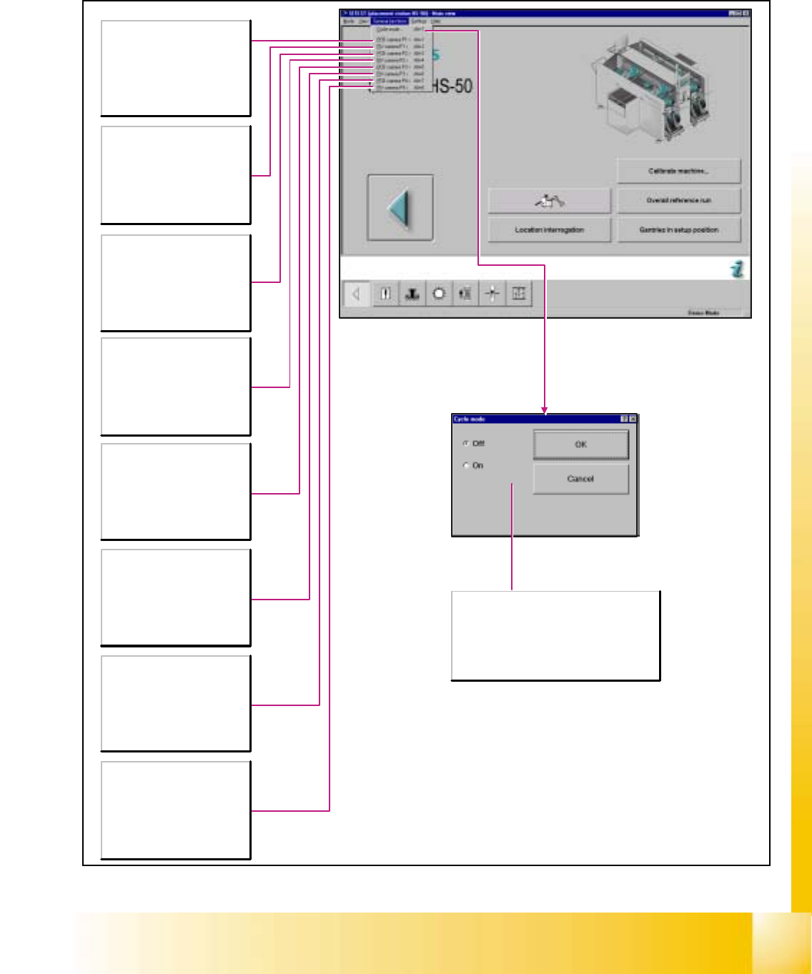
6.3.5 Menu Bar: General Functions
6
Alt+1
Switches the screen display to
the PCB camera fitted to gantry
1.
Press the ESC button to switch
the screen display back to the
normal test program mode.
Alt+2
Switches the screen display to
the camera fitted to revolver
head 1.
Press the ESC button to switch
the screen display back to the
normal test program mode.
Alt+3
Switches the screen display to
the PCB camera fitted to gantry
2.
Press the ESC button to switch
the screen display back to the
normal test program mode.
Alt+4
Switches the screen display to
the camera fitted to revolver
head 2.
Press the ESC button to switch
the screen display back to the
normal test program mode.
Alt+5
Switches the screen display to
the PCB camera fitted to gantry
3.
Press the ESC button to switch
the screen display back to the
normal test program mode.
Alt+6
Switches the screen display to
the camera fitted to revolver
head 3.
Press the ESC button to switch
the screen display back to the
normal test program mode.
Alt+7
Switches the screen display to
the PCB camera fitted to gantry
4.
Press the ESC button to switch
the screen display back to the
normal test program mode.
Alt+8
Switches the screen display to
the camera fitted to revolver
head 4.
Press the ESC button to switch
the screen display back to the
normal test program mode.
Off
Deactivates the cycle mode.
On
Activates the cycle mode. The Start button on
the machine must be pressed for each step of
the placement process.