HS50_advance_level 1_20200522_221201 (1).pdf - 第198页
06/2002 E dition Studen t Guide H S-50 Advance d I 6 Operati ng the S IT ES T Softwa r e 14 6.3.7 Menu Ba r : H elp 6 Opens the table of c onte n ts of t h e onli ne h elp. Des c rip tio n of t he co mm ands th at can be…
Student Guide HS-50 Advanced I 06/2002 Edition
6 Operating the SITEST Software
13
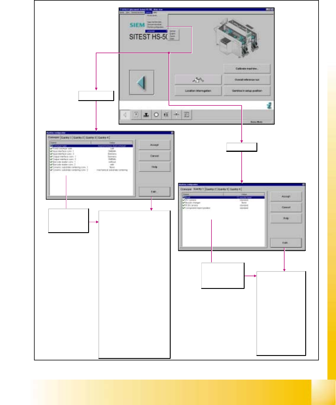
6.3.6.2 Machine Configuration
6
Displays the current
machine configuration
for the conveyor and
may be changed, if
required.
Displays the current
machine configuration
for gantry 1 to 4 and
may be changed, if
required.
Conveyor selected
Conveyor type
- Single conveyor
- Synchronous dual conveyor
- Asynchronous dual conveyor
Fixed conveyor side
- left: The fixed side of the conveyor is
located on the left (viewing into the
direction of travel).
- right: The fixed side of the conveyor is
located on the right (viewing into the
direction of travel).
Input interface conv. 1/2
Here you can select the input interface
type for conveyor 1/2.
- SMEMA
- Siemens
Output interface conv. 1/2
Here you can select the output interface
type for conveyor 1/2.
- SMEMA
- Siemens
Barcode reader conv. 1/2
- without
- with
Ceramic substrate centering conv. 1/2
- None
- Mechanical substrate centering
- Oblique lighting
- Mechanical and oblique lighting
Gantry selected
Head
- 12-nozzle head: Revolver
head with 12 sleeves.
RV camera
- standard
- DCA camera
Nozzle changer
- None
- RV12 standard
- RV12 2-row
PCB camera
- Standard
- Multicolor
Component reject position
- Standard
06/2002 Edition Student Guide HS-50 Advanced I
6 Operating the SITEST Software
14
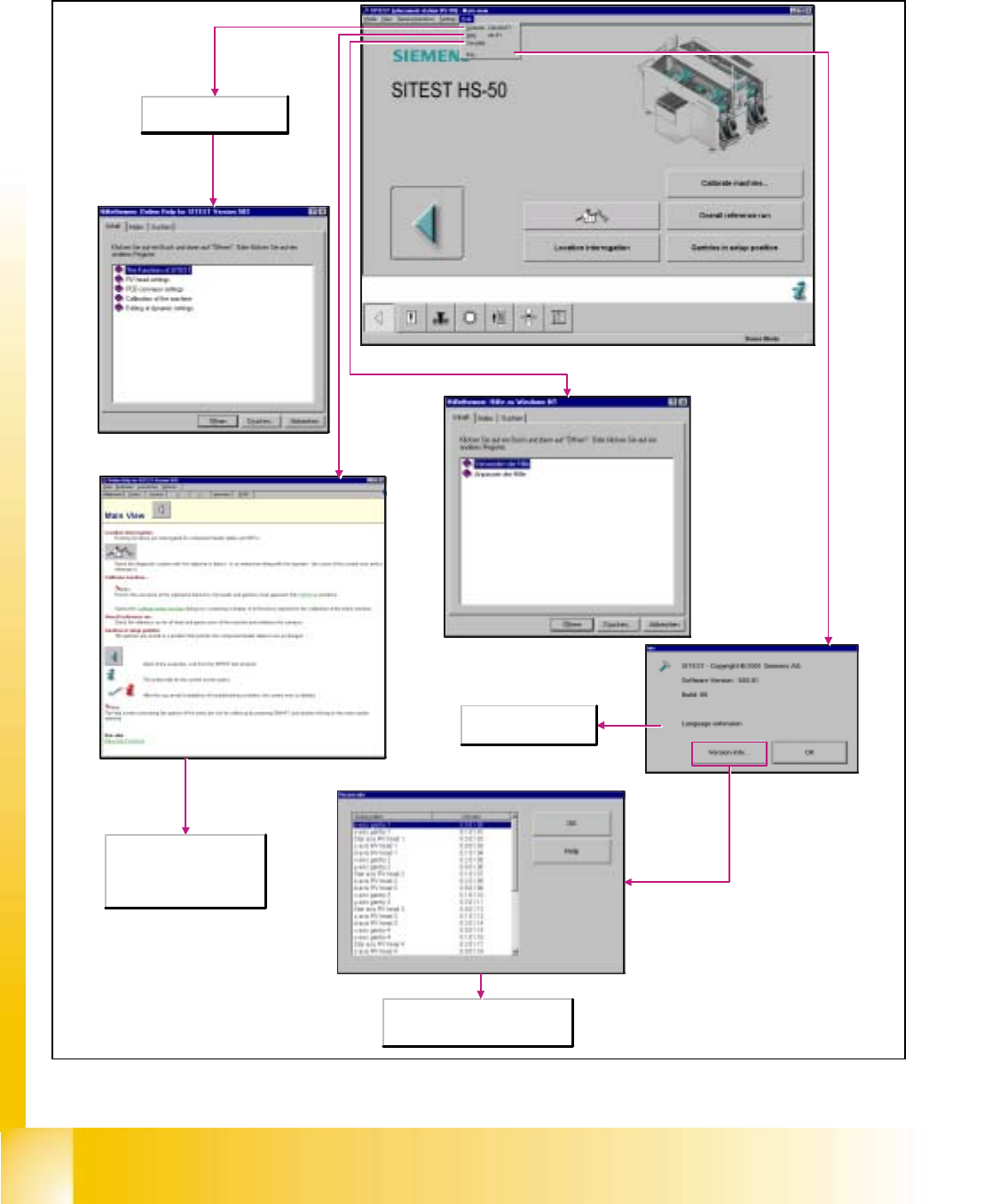
6.3.7 Menu Bar: Help
6
Opens the table of contents
of the online help.
Description of the commands
that can be executed in the
currently open window. Call-up
of the context-sensitive help
system by pressing <Alt> <F1>.
Shows information about the
subsystems and the corresponding
version information.
Displays information
about the current version.
Student Guide HS-50 Advanced I 06/2002 Edition
6 Operating the SITEST Software
15
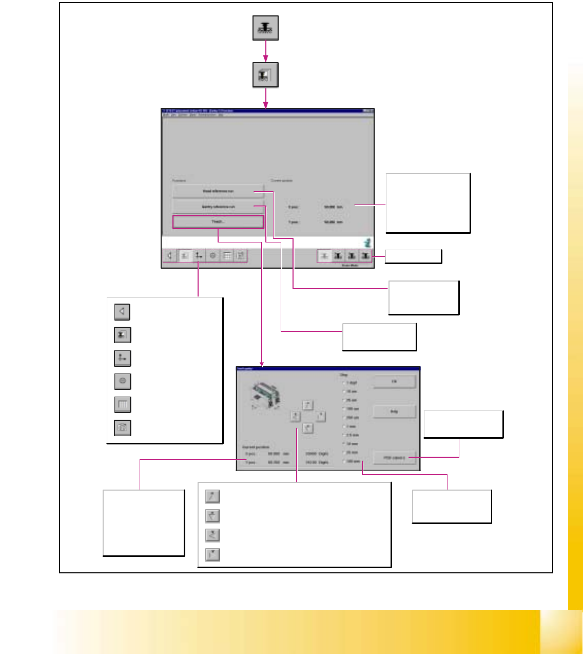
6.4 Gantries
6.4.1 Gantry Functions
6
Call-up of the gantry functions.
Call-up of the display of the
gantry axis functions.
Call-up of the display of the
gantry's calibration functions.
Call-up of the display of the
gantry's PCB mapping
functions.
Call-up of the display of the
gantry's PCB camera
functions.
Return to the main view.
Current position
X-pos.
Indicates the current x-position
of the applicable gantry.
Y-pos.
Indicates the current y-position
of the applicable gantry.
PCB camera
Switches the screen display to
the PCB camera.
Step
The desired step size for
traversing the gantry can be
activated in a given resolution.
Upon each actuation of the button, the active gantry is advanced by
one increment of the selected step size in negative y-direction.
Upon each actuation of the button, the active gantry is advanced by
one increment of the selected step size in positive y-direction.
Upon each actuation of the button, the active gantry is advanced by
one increment of the selected step size in negative x-direction.
Upon each actuation of the button, the active gantry is advanced by
one increment of the selected step size in positive x-direction.
Selects gantry 1-4.
Head reference run
Carries out the reference
run on all axes of the
revolver head.
Gantry reference run
Carries out the reference
run of the gantry axes.
X-pos.
Indicates the applicable
gantry's x-position
approached during teaching.
Y-pos.
Indicates the applicable
gantry's y-position
approached during teaching.