HS50_advance_level 1_20200522_221201 (1).pdf - 第206页
06/2002 E dition Studen t Guide H S-50 Advance d I 6 Operati ng the S IT ES T Softwa r e 22 6. 5 Revo lver Heads 6. 5. 1 F un ct io ns of t he R e vol v er He ad Step star axi s This f unction is used to i ndex the star.…
Student Guide HS-50 Advanced I 06/2002 Edition
6 Operating the SITEST Software
21
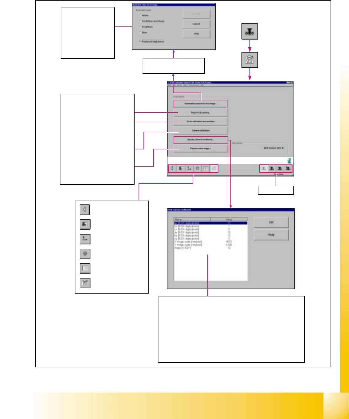
6.4.5 Gantry‘s PCB Camera Functions
Call-up of the gantry functions.
Call-up of the display of the
gantry axis functions.
Call-up of the display of the
gantry's calibration functions.
Call-up of the display of the
gantry's PCB mapping
functions.
Call-up of the display of the
gantry's PCB camera
functions.
Return to the main view.
This function can only be selected if
the multicolor camera was selected in
the machine configuration.
Teach PCB camera...
Opens the Teach PCB camera dialog box
and displays the current position of the
gantry that was approached last.
Go to calibration tool position
Moves the active gantry with the PCB
camera mounted to it over the calibration
tool position and switches the screen
display to the PCB camera.
Calibrate camera
Determines the sensor scale (nm/pixel)
and the camera angle.
Pseudo-color image >
Switches the screen display to the PCB
camera to view the result of any
illumination changes that may have been
made.
Here, a functional check of the
camera and the illumination
unit is carried out due to the
fact that the IR illumination
levels involve infrared rays that
are invisible to the human eye.
Reduced brightness
Activate this function in the
case of excessive brightness of
the camera image.
Selects gantry 1-4.
The values ax, bx, cx, ay, by and cy describe a homogenous transformation matrix.
This matrix is the transformation from the machine coordinate system [digits] to the
camera [pixels].
X image scale [nm/pixel]
Indicates the calculation of the xµ values. These denote the dimensions of the pixels [nm]
with respect to the machine axis.
Y image scale [nm/pixel]
Indicates the calculation of the xµ values. These denote the dimensions of the pixels [nm]
with respect to the machine axis.
Angle [1/100*]
Indicates the angular position of the camera with respect to the machine coordinate
system.
06/2002 Edition Student Guide HS-50 Advanced I
6 Operating the SITEST Software
22
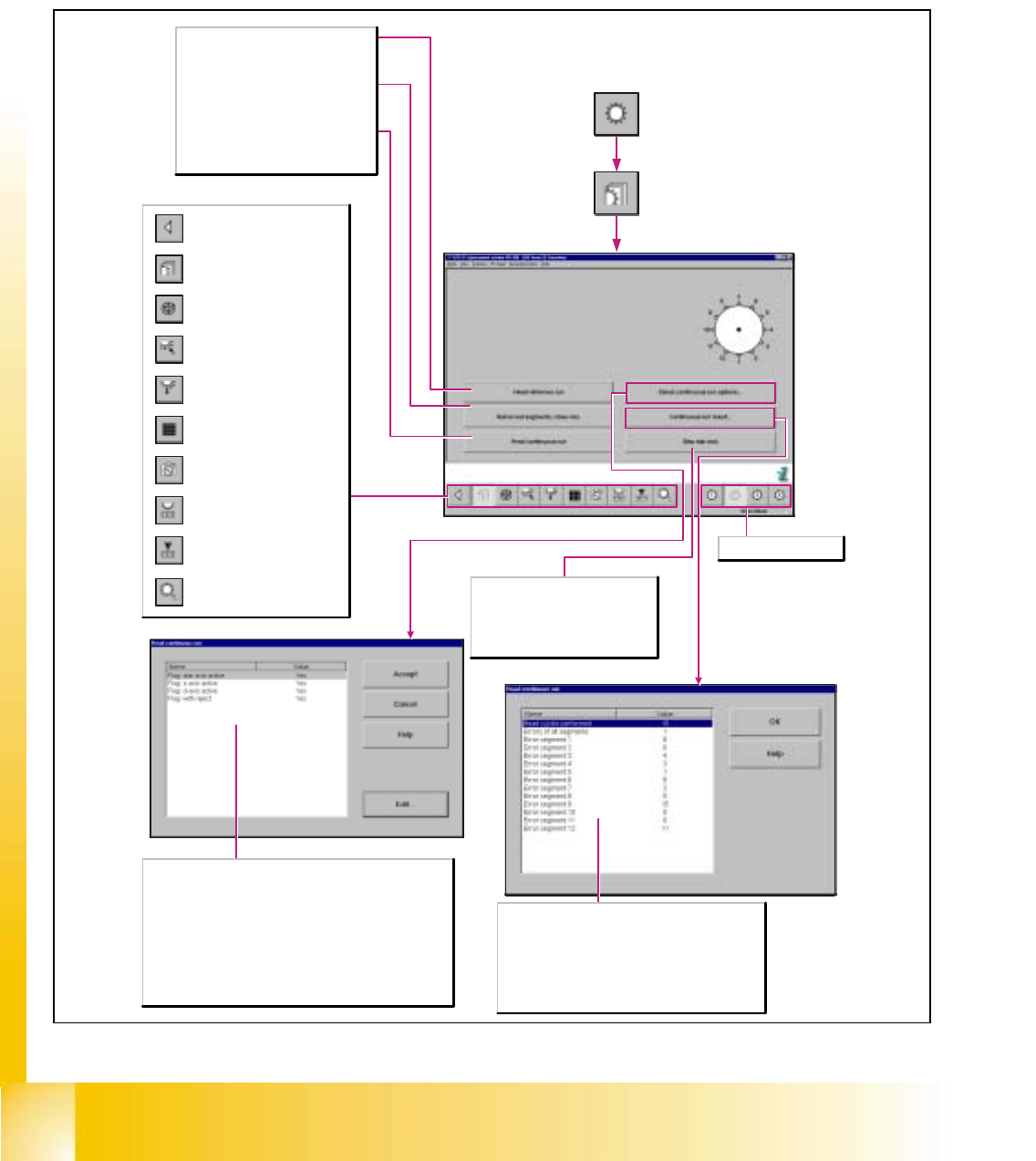
6.5 Revolver Heads
6.5.1 Functions of the Revolver Head
Step star axis
This function is used to index the star.
Every time you click on the button the
star is advanced by one segment. The
positions of the individual segments are
displayed graphically on the screen.
Head cycles performed
Displays the number of head cycles performed during the
head continuous run.
Errors of all segments
Displays the number of errors of all segments.
Errors of segments 1-12
Displays the number of errors for each segment.
Head reference run
Carries out the Reference run on all axes of
the revolver head on the activated gantry.
Swivel out segments/close noz.
Moves the sleeves to the 0-degree position
and closes the vacuum at the nozzles.
Head continuous run
Starts the continuous run and opens a
dialog window displaying the start time and
the completion time.
Opening the screen for the
magazin functions of the
revolver head nozzle changer
Return to the main
view.
Call-up the view for the functions
of the revolver head component
sensor.
Opening the screen for the head
functions of the revolver head
nozzle changer
Call-up of the display of the RV
camera functions.
Call-up of the display of the
mapping functions of the
revolver head.
Call-up of the display of the
functions of the revolver head in
the placement and pick-up
circuit.
Call-up of the display of the
functions of the revolver head in
the holding and reject circuit.
Call-up of the display of the axis
functions of the revolver head.
Call-up of the display of the
functions of the revolver head.
Flag: star axis active
Activates or deactivates the star axis during the head continuous run.
Flag: z-axis active
Activates or deactivates the star axis during the head continuous run.
Flag: d-axis active
Activates or deactivates the star axis during the head continuous run.
Flag: with reject
Activates or deactivates during the head continuous run the approach
of the reject position for discarding the components.
Selects revolver head 1-4.
Student Guide HS-50 Advanced I 06/2002 Edition
6 Operating the SITEST Software
23
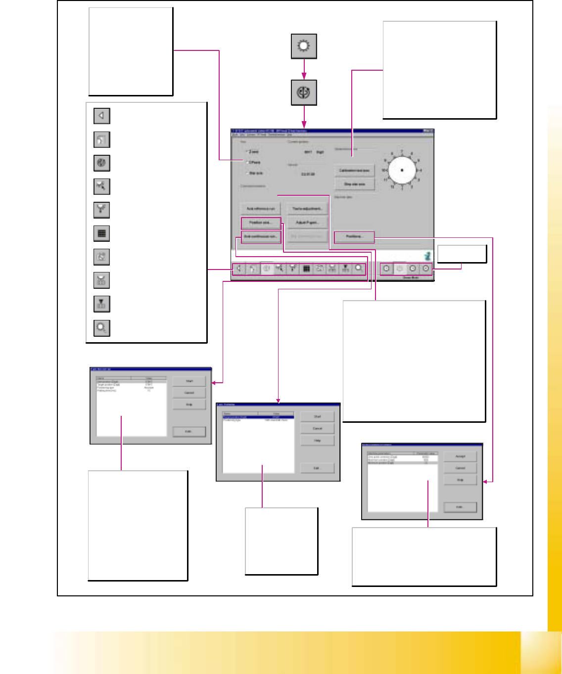
6.5.2 Axis Functions of the Revolver Head
Axis
Z-axis
Activates the functions for the
settings of the z-axis.
DP-axis
Activates the functions for the
settings of the dp-axis.
Star axis
Activates the functions for the
settings of the star axis.
Target position [digits]
Enter the desired target
position for the selected
axis.
Positioning type
Defines the method to
be used for positioning
the axis.
Opening the screen for the
magazin functions of the
revolver head nozzle changer
Return to the main
view.
Call-up the view for the functions
of the revolver head component
sensor.
Opening the screen for the head
functions of the revolver head
nozzle changer
Call-up of the display of the RV
camera functions.
Call-up of the display of the
mapping functions of the
revolver head.
Call-up of the display of the
functions of the revolver head in
the placement and pick-up
circuit.
Call-up of the display of the
functions of the revolver head in
the holding and reject circuit.
Call-up of the display of the axis
functions of the revolver head.
Call-up of the display of the
functions of the revolver head.
Zero point cor.value [digits]
Corrects the reference point by the preset value.
Maximum position [digits]
Indicates the maximum attainable position of the axis.
Minimum position [digits]
Indicates the minimum attainable position of the axis.
Selects revolver
head 1-4.
Start position [digits]
Enter the desired start position for
the selected axis.
Target position [digits]
Enter the desired target position for
the selected axis.
Positioning type
Defines the method to be used for
positioning the axis.
Waiting time [msec]
Indicates the length of time the axis
is to remain in the start and/or target
position during the continuous run.
Common functions
Axis reference run...
Performs a reference run of the activated axis.
Tacho adjustment...
Starts the continuous run for adjusting the speed of
the selected axis and opens the Tacho adjustment
dialog box for the display of the values determined.
Adjust P-gain...
Opens the Adjust P-gain dialog box for presetting the
required parameters.
Star continuous run
Opens the Axis continuous run dialog box for
presetting the waiting time of the axis continuous run
and for indexing the star axis in the continuous run.
General functions
Calibration tool pos.
During the adjustment of the P-gain of the
z-axis, the active gantry approaches the
calibration tool position, and then moves
the z-axis to the calibration tool pocket in
the continuous run mode.
Step star axis
This function is used to index the star.
Clicking on the button causes the star to
be advanced by one segment. The
positions of the individual segments are
represented graphically on the screen.