HS50_advance_level 1_20200522_221201 (1).pdf - 第219页
Studen t Guide HS-50 A dvanced I 06/200 2 Edition 6 Operat ing the S ITE ST S o ftware 35 6.6 PCB Conveyor 6.6. 1 Scree n Displayi ng of the PCB T ran sport Funct ion Call -up t he Co nveyor Func tion s view. Call -up t …
06/2002 Edition Student Guide HS-50 Advanced I
6 Operating the SITEST Software
34
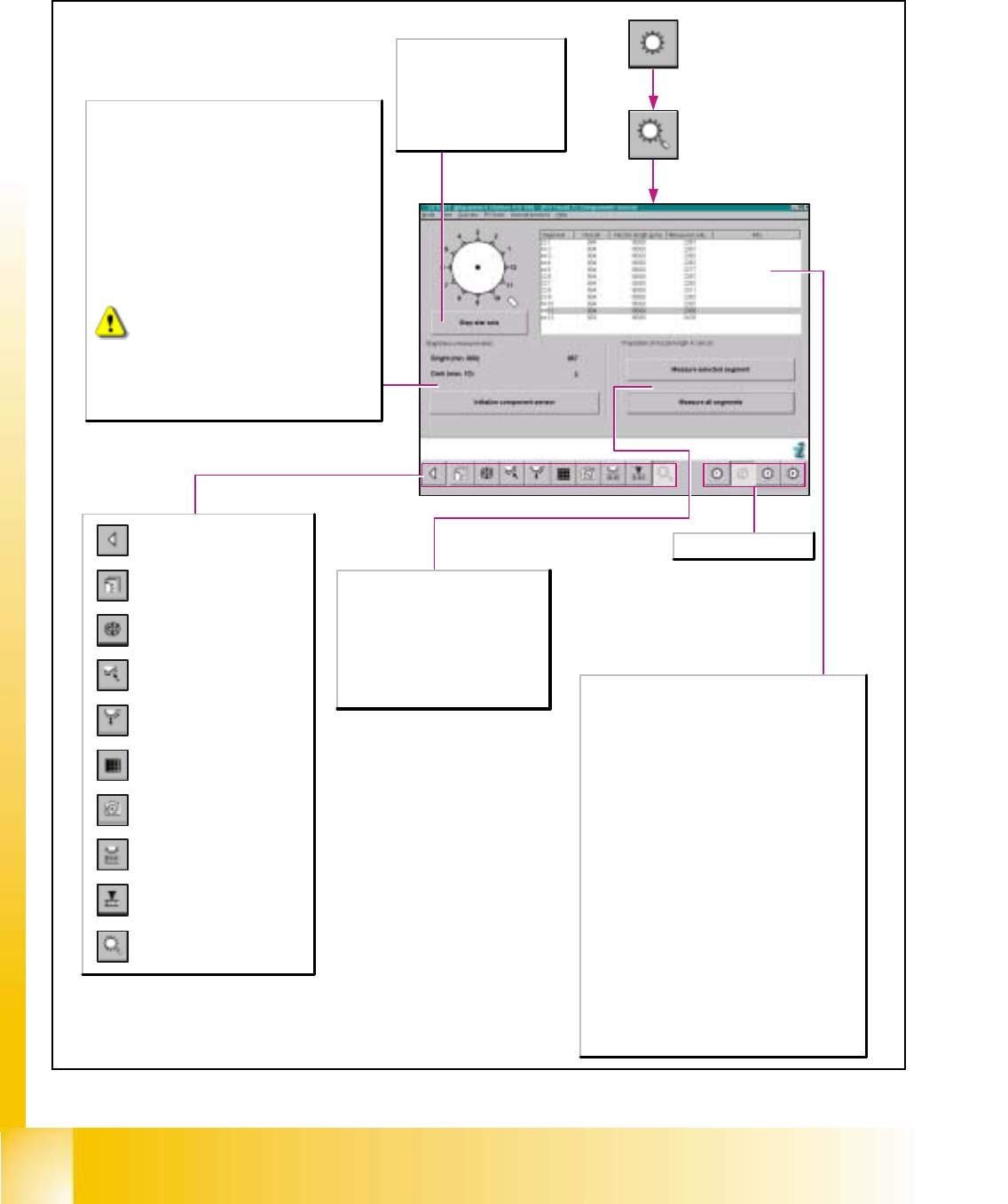
6.5.12 Revolver Head Component Sensor
Opening the screen for the
magazin functions of the
revolver head nozzle changer
Return to the main
view.
Call-up the view for the functions
of the revolver head component
sensor.
Opening the screen for the head
functions of the revolver head
nozzle changer
Call-up of the display of the RV
camera functions.
Call-up of the display of the
mapping functions of the
revolver head.
Call-up of the display of the
functions of the revolver head in
the placement and pick-up
circuit.
Call-up of the display of the
functions of the revolver head in
the holding and reject circuit.
Call-up of the display of the axis
functions of the revolver head.
Call-up of the display of the
functions of the revolver head.
Brightness measurements
Bright
Shows the bright value in [Digit] from the initialization of
the component sensor. The component sensor was
switched on during the measurement.The minimum
permitted bright value of the component sensor is shown
in parentheses.
Range: 800 - 1024 [Digit]
Dark
Shows the dark value in [Digit] from the initialization of the
component sensor. The component sensor was switched
off during the measurement.The maximum permitted dark
value of the component sensor is shown in parentheses.
Range: 0 -10 [Digit]
Initialize component sensor
Carries out a head reference run with all axes of the
revolver head on the active gantry and checks whether a
component sensor is present.The bright/dark
measurement is taken and displayed.
is displayed if the bright/dark measurements
do not lie within the specified limit values for
the bright/dark values.
Step star axis
This function permits the star
to be advanced step by step.
Every time this button is
clicked, the star is advanced by
one segment. The positions of
the individual segments are
displayed on the screen.
Selects revolver head 1-4.
Proportion of nozzle length in sensor
Measure selected segment
Measures the segment selected in the
list, enters the value determined and
takes this as a reference value.
Measure all segments
Measures all segments, enters the
values determined and takes these as
reference values.
List of measured values
Segment
Segment number of the nozzle and status of
measurement determination
White:
Measurement determination has not yet been
carried out for this segment.
Green:
Measurement determination has been carried
out for this segment.
Grey:
Measurement determination is not possible for
this segment.
Nozzle:
Shows what nozzle is located on the segment
Nozzle length [µm]:
Shows the nominal length of the nozzle.
Measured value [µm]:
Shows the measured nozzle length and the length of the
field of vision of the component sensor.
Info:
Shows the status of the measurement or issues an error
message.
Student Guide HS-50 Advanced I 06/2002 Edition
6 Operating the SITEST Software
35
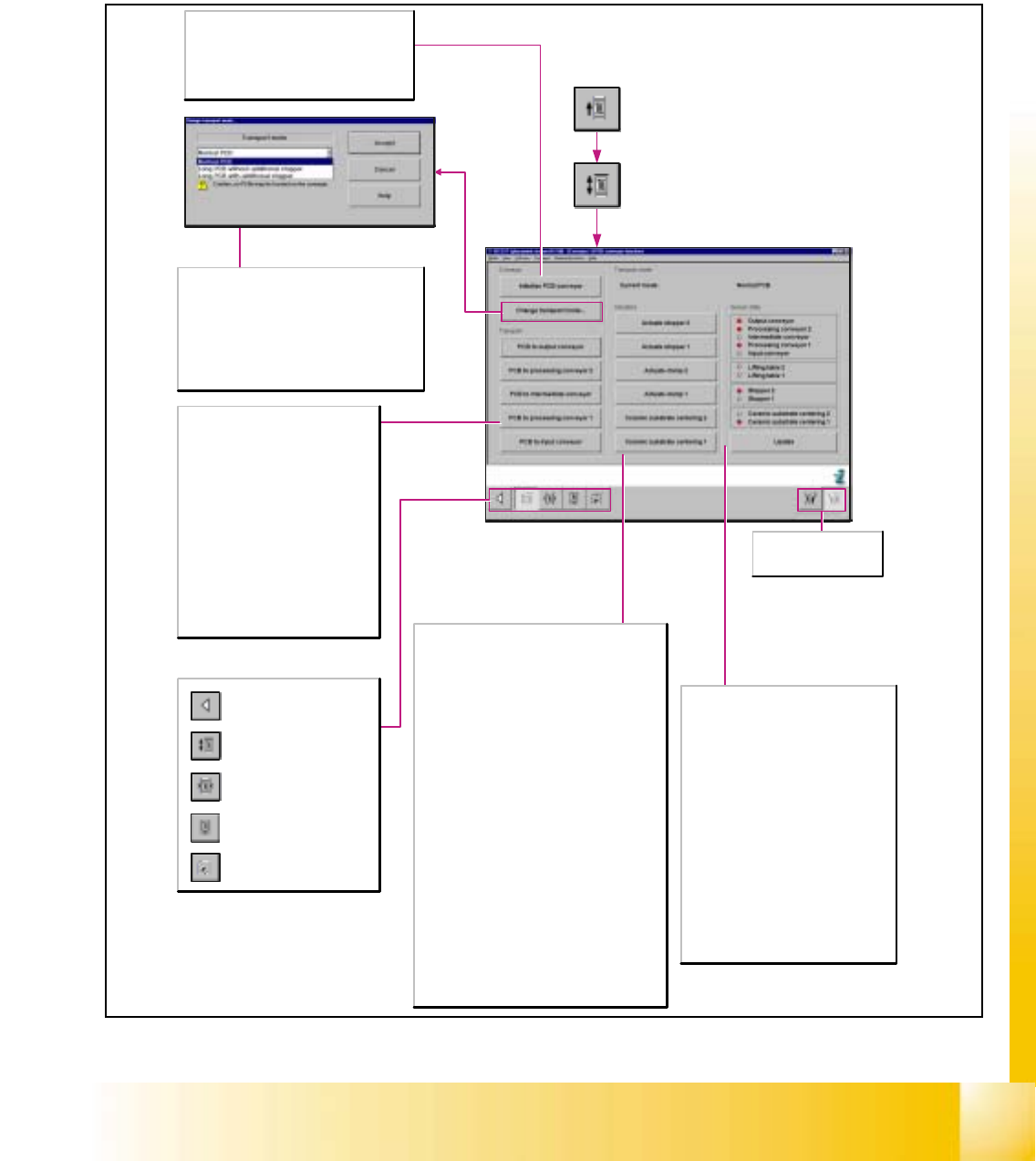
6.6 PCB Conveyor
6.6.1 Screen Displaying of the PCB Transport Function
Call-up the Conveyor Functions
view.
Call-up the screen for setting
the conveyor speed.
Not for SIPLACE S-25HM!
Call-up of the display of the
conveyor width settings.
Call-up the screen displaying
the PCB transport functions.
Return to the main view.
Transporting
PCB to output conveyor
Transports the PCB from the processing
conveyor 2 to the output conveyor.
PCB to processing conveyor 2
Transports the PCB to the processing
conveyor 2.
PCB to intermediate conveyor
Transports the PCB from the processing
conveyor 1 to the intermediate conveyor.
PCB to processing conveyor 1
Transports the PCB to the processing
conveyor 1.
PCB to input conveyor
Transports the PCB to the input conveyor.
Actuators
Actuate stopper 2
The PCB stopper of processing conveyor 2 is either
retracted or extended, depending on the current state.
Actuate stopper 1
The PCB stopper of processing conveyor 1 is either
retracted or extended, depending on the current state.
Note:
If the Actuate stopper 1/2 buttons are deactivated, the
machine is fitted with laser light barriers.
For SIPLACE HS-55 only.
Actuate clamp 1
The PCB on the processing conveyor 2 is either
clamped or unclamped, depending on the current
state.
Actuate clamp 2
The PCB on processing conveyor 1 is either clamped
or unclamped, depending on the current state.
Ceramic substrate centering 2
Option: A ceramic substrate on processing conveyor 2
is either clamped or unclamped, depending on the
current state.
Ceramic substrate centering 1
Option: A ceramic substrate on processing conveyor 1
is either clamped or unclamped, depending on the
current state.
Sensor state
Indicates the current state of the ultrasonic
sensors of the individual conveyors and
actuators. The current states of the ultrasonic
sensors are indicated by associated LED
symbols:
gray: not activated
red: activated
Update
Updates the status display of the ultrasonic
sensors of the individual conveyors and
actuators.
This functions may also be used for testing
the proper response of the ultrasonic
sensors. They may have to be readjusted, as
required.
Note:
The SIPLACE HS-55 uses laser light barriers
in place of ultrasound sensors.
Selects PCB conveyor 1/2
(in the case of dual lane
conveyors).
Conveyor
Initialize PCB conveyor
All conveyors, except for the input conveyor, are
moving at high speed.
To check the transport functions without
performing an overall reference run, it is
necessary to initialize the PCB conveyor system.
Transport mode
The following transport modes are available:
- normal PCB (up to 368 mm)
- long PCB without additional stopper (up to 610 mm)
- long PCB with additional stopper (up to 610 mm)
Note:
If you have selected the long PCB with additional
stopper transport mode, it is not possible to teach the
PCB reference corners.
06/2002 Edition Student Guide HS-50 Advanced I
6 Operating the SITEST Software
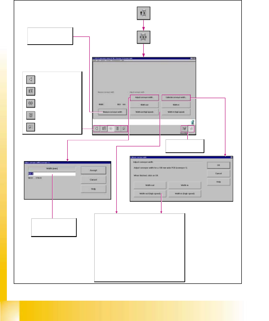
36
6.6.2 Conveyor Width Settings
Measure conveyor width
Measures the current conveyor
width and displays the value
above the applicable button.
Adjusting the conveyor width
Width-out
The width of the conveyors will be increased when the button is
actuated.
Width-out (high speed)
The width of the conveyors is increased at high speed when the
button is actuated.
Calibrate conveyor width
Determines the gantry position for a 100mm wide PCB.
Width-in
The width of the conveyors will be decreased when the button is
actuated.
Width-in (high speed)
The width of the conveyors is decreased at high speed when the
button is actuated.
Call-up the Conveyor Functions
view.
Call-up the screen for setting
the conveyor speed.
Not for SIPLACE S-25HM!
Call-up of the display of the
conveyor width settings.
Call-up the screen displaying
the PCB transport functions.
Return to the main view.
Selects PCB conveyor 1/2
(in the case of dual lane
conveyors).
Width [mm/10]
Enter the desired conveyor
width (within the specified value
range) in the data entry field.