HS50_advance_level 1_20200522_221201 (1).pdf - 第233页
Studen t Guide HS-50 A dvanced I 06/200 2 Edition 7 Calibration 3 0 fig 7.3 - 1 Ca libra te enti re machi ne S IPL ACE H S-5 0/H S- 55 0 fig 7 .2 - 2 Start th e ca libra tio n pro cedu re fo r th e en tire mach in e 0 Cl…
06/2002 Edition Student Guide HS-50 Advanced I
7 Calibration
2
0
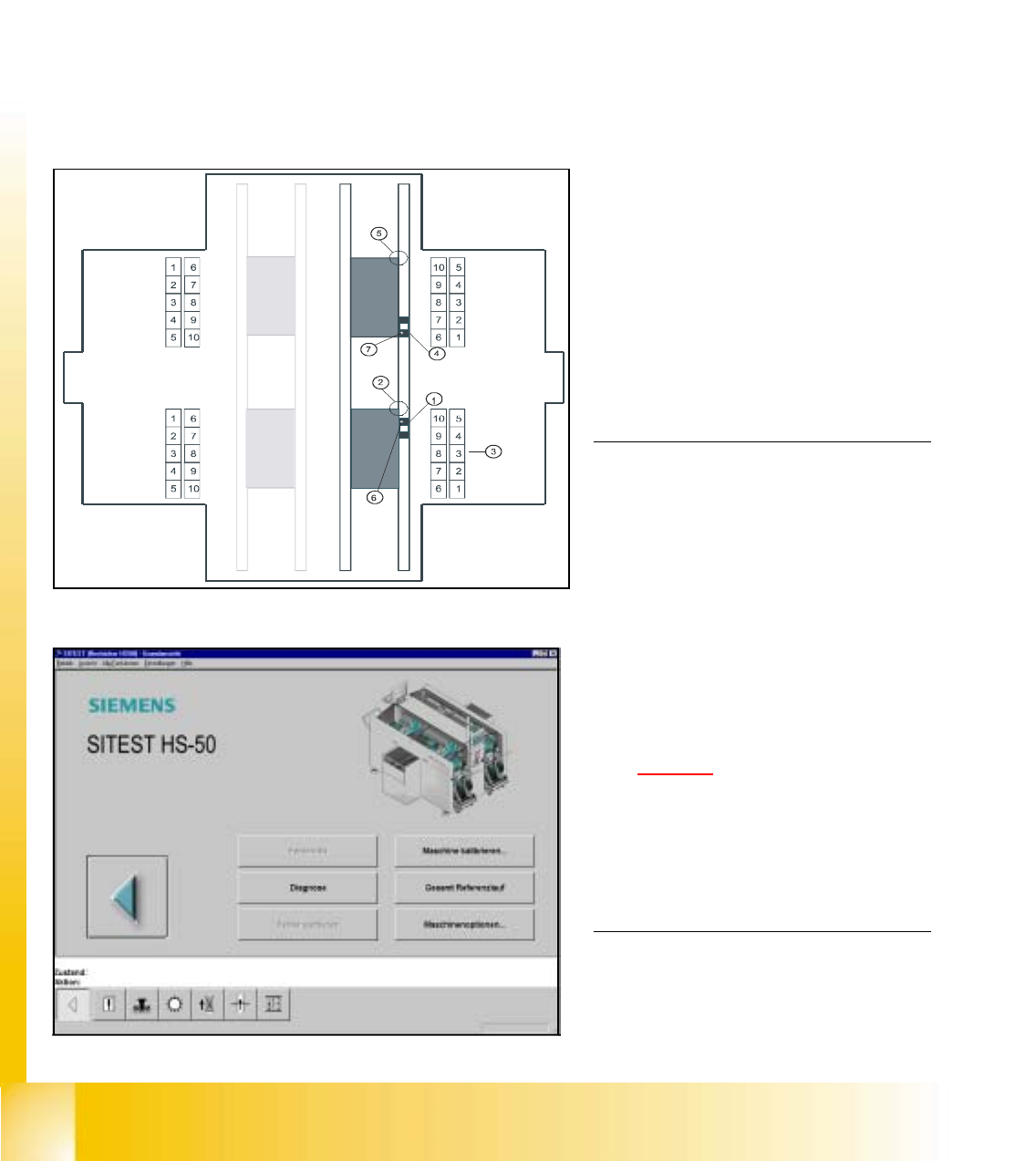
fig 7.1 - 1 Top view of machine
0
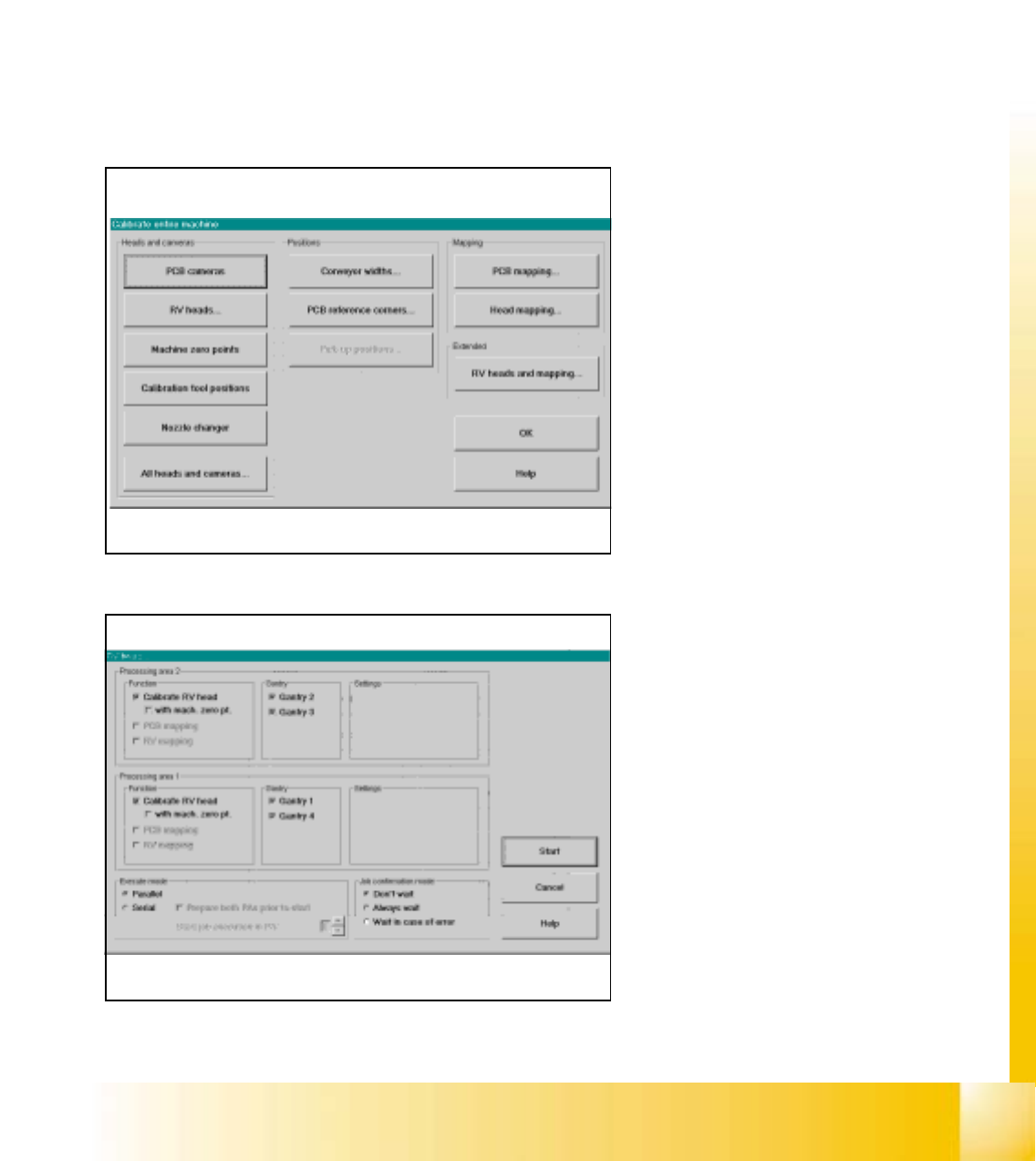
fig 7.3 - 2 Main view SIPLACE HS-50
KEY:
(1) Calibration position BB 1
(2) Fixed PCB corner BB 1
(3) Nozzle changer magazine
(4) Calibration position BB 2
(5) Fixed PCB corner BB 2
(6) Machine zero point BB 1
(7) Machine zero point BB 2
NOTE
Some calibrations require that you attach
ozzles on the placement heads.
Use nozzles of type 956.
Make sure that all nozzles have been
attached correctly, otherwise measuring
will lead to incorrect results.
If you need to, place the calibration tool
into the "calibration bag".
(See fig 7.1 - 1
).
Before you place the calibration tool, make
sure that it is clean. Also, be sure that you
insert it into the "calibration bag" with its
print of the fiducial structure on the bot-
tom. 0
7.1 Preparation for Calibration
à Start SITEST.
à Under menu item "Main view", click "Overall reference run", to reference all gantry- and head- axes.
Student Guide HS-50 Advanced I 06/2002 Edition
7 Calibration
3
0
fig 7.3 - 1 Calibrate entire machine SIPLACE HS-50/HS-55
0
fig 7.2 - 2 Start the calibration procedure for the entire machine
0
Click the button "All Heads and Cameras"
to start the calibration procedure of the en-
tire machine. 0
If you want to calibrate only e.g. the PCB
cameras, please use the button "PCB
cameras to calibrate all PCB cameras on
all gantries. 0
0
0
0
0
0
0
0
0
0
0
0
0
0
0
0
In this menue you can use all fixed settings
and with the button "Start" the automati-
cally calibration procedure starts. 0
0
7.2 Calibration of the entire machine
à Place the a calibration tool into the "calibration bag"from the placement area 1and 2.
à Calibrations require that you attach nozzles on the placement heads. Use nozzles of type 956.
à Start SITEST and confirm the nozzle configuration in the Sitest for all C&P heads.
à Under menu item "Main view", click "Overall reference run", to reference all gantry- and head- axes.
à Under menu item "Main view", click "Calibrate machine...", to calibrate all heads and cameras.
7
06/2002 Edition Student Guide HS-50 Advanced I
7 Calibration
4
0
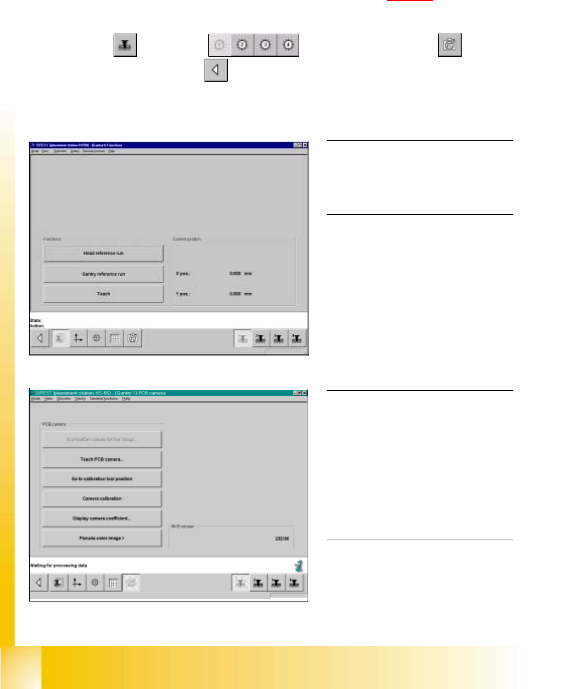
fig 7.3 - 1 Display: "Gantry functions"
0
fig 7.3 - 2 Display "PCB camera functions"
7.3 Single calibration steps
7.3.1 Calibration of PCB - Camera
Example: PCB - camera, gantry 1 7
7
à Insert the calibration tool into the "calibration bag " in placement area 1. (See fig 7.1 - 1).
SITEST: 7
à Select "Gantry" ==> "Gantry 1" ==> "PCB - camera functions" ==>
"Calibrate camera" ==> "Main view" ==> "Settings" ==> "Save machine data".
NOTE
Repeat these instructions in order to
calibrate the PCB - cameras of gantries
2, 3 and 4. 0
0
0
0
0
0
0
0
0
0
0
0
0
NOTE
With the help of the function "Display
camera coefficient", the determined
values can be displayed after you finished
calibration.
The value under "Angle [1 / 100°] must not
exceed 100. 0