HS50_advance_level 1_20200522_221201 (1).pdf - 第234页
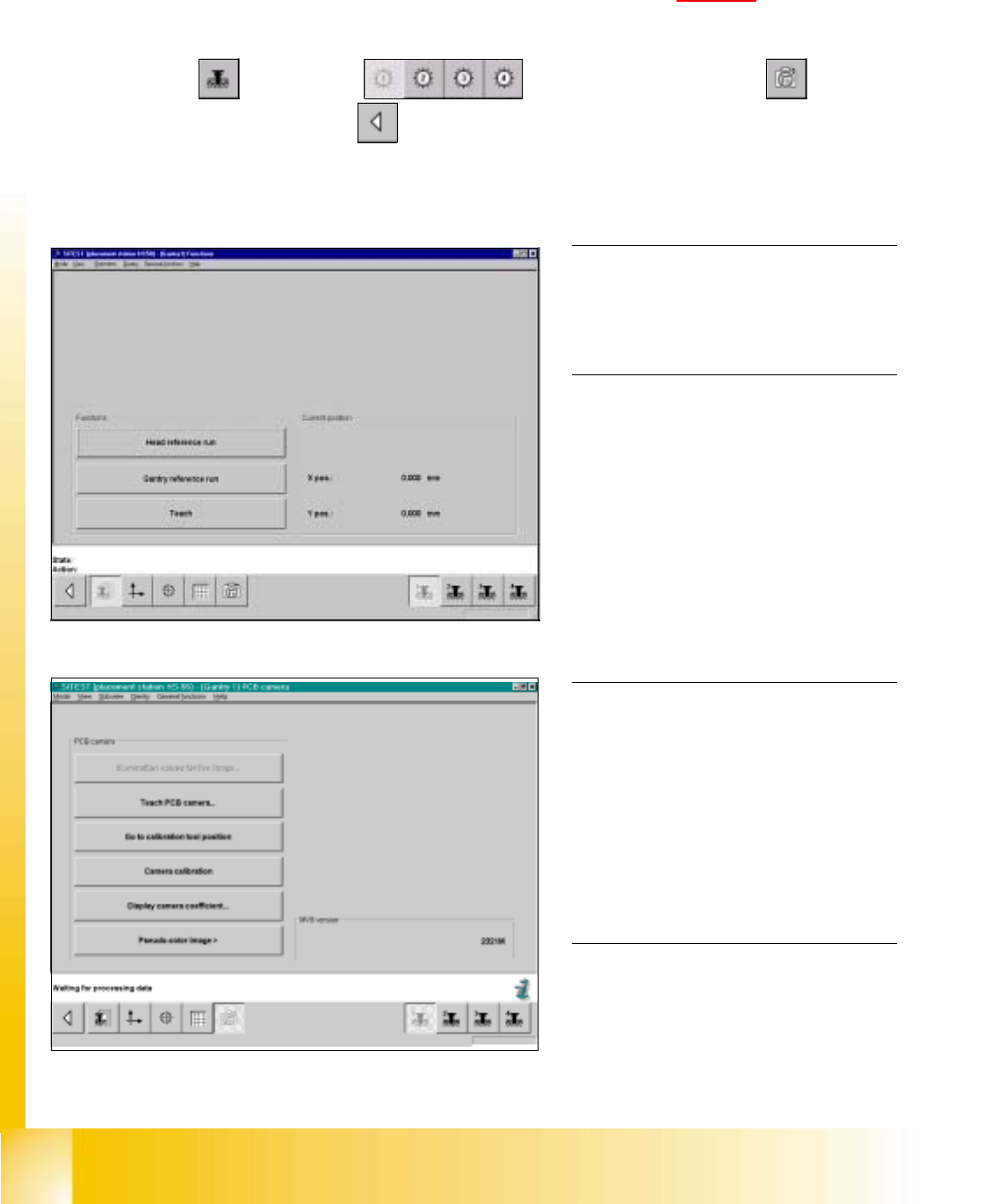
06/2002 E dition Studen t Guide H S-50 Advance d I 7 Calibr ation 4 0 fi g 7.3 - 1 D isp la y: "Gan tr y fu nc tion s" 0 f ig 7 .3 - 2 Displ ay " PCB ca mera fu nction s" 7.3 Single calibr ation ste p…
Student Guide HS-50 Advanced I 06/2002 Edition
7 Calibration
3
0
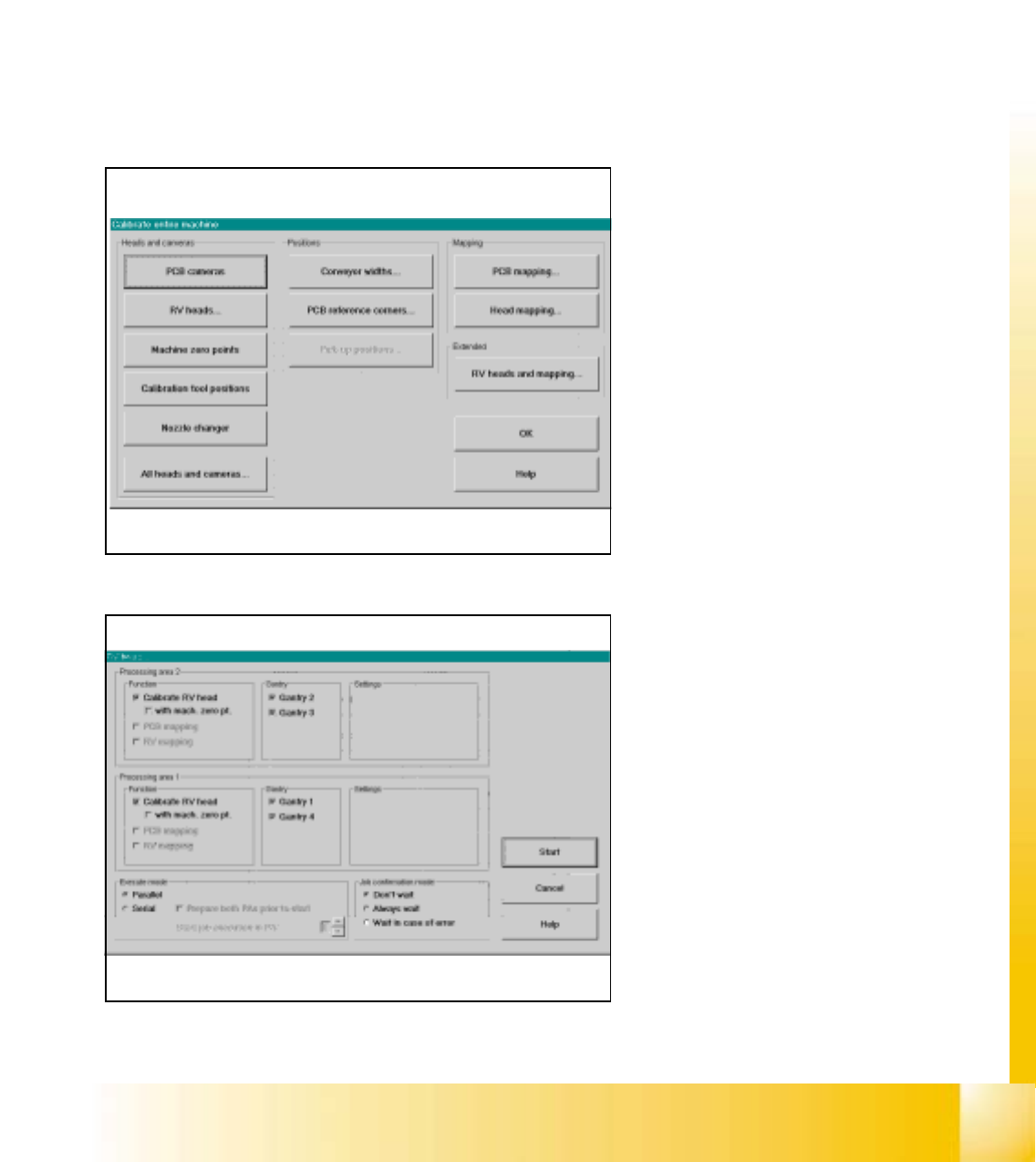
fig 7.3 - 1 Calibrate entire machine SIPLACE HS-50/HS-55
0
fig 7.2 - 2 Start the calibration procedure for the entire machine
0
Click the button "All Heads and Cameras"
to start the calibration procedure of the en-
tire machine. 0
If you want to calibrate only e.g. the PCB
cameras, please use the button "PCB
cameras to calibrate all PCB cameras on
all gantries. 0
0
0
0
0
0
0
0
0
0
0
0
0
0
0
0
In this menue you can use all fixed settings
and with the button "Start" the automati-
cally calibration procedure starts. 0
0
7.2 Calibration of the entire machine
à Place the a calibration tool into the "calibration bag"from the placement area 1and 2.
à Calibrations require that you attach nozzles on the placement heads. Use nozzles of type 956.
à Start SITEST and confirm the nozzle configuration in the Sitest for all C&P heads.
à Under menu item "Main view", click "Overall reference run", to reference all gantry- and head- axes.
à Under menu item "Main view", click "Calibrate machine...", to calibrate all heads and cameras.
7
06/2002 Edition Student Guide HS-50 Advanced I
7 Calibration
4
0
fig 7.3 - 1 Display: "Gantry functions"
0
fig 7.3 - 2 Display "PCB camera functions"
7.3 Single calibration steps
7.3.1 Calibration of PCB - Camera
Example: PCB - camera, gantry 1 7
7
à Insert the calibration tool into the "calibration bag " in placement area 1. (See fig 7.1 - 1).
SITEST: 7
à Select "Gantry" ==> "Gantry 1" ==> "PCB - camera functions" ==>
"Calibrate camera" ==> "Main view" ==> "Settings" ==> "Save machine data".
NOTE
Repeat these instructions in order to
calibrate the PCB - cameras of gantries
2, 3 and 4. 0
0
0
0
0
0
0
0
0
0
0
0
0
NOTE
With the help of the function "Display
camera coefficient", the determined
values can be displayed after you finished
calibration.
The value under "Angle [1 / 100°] must not
exceed 100. 0
Student Guide HS-50 Advanced I 06/2002 Edition
7 Calibration
5
0
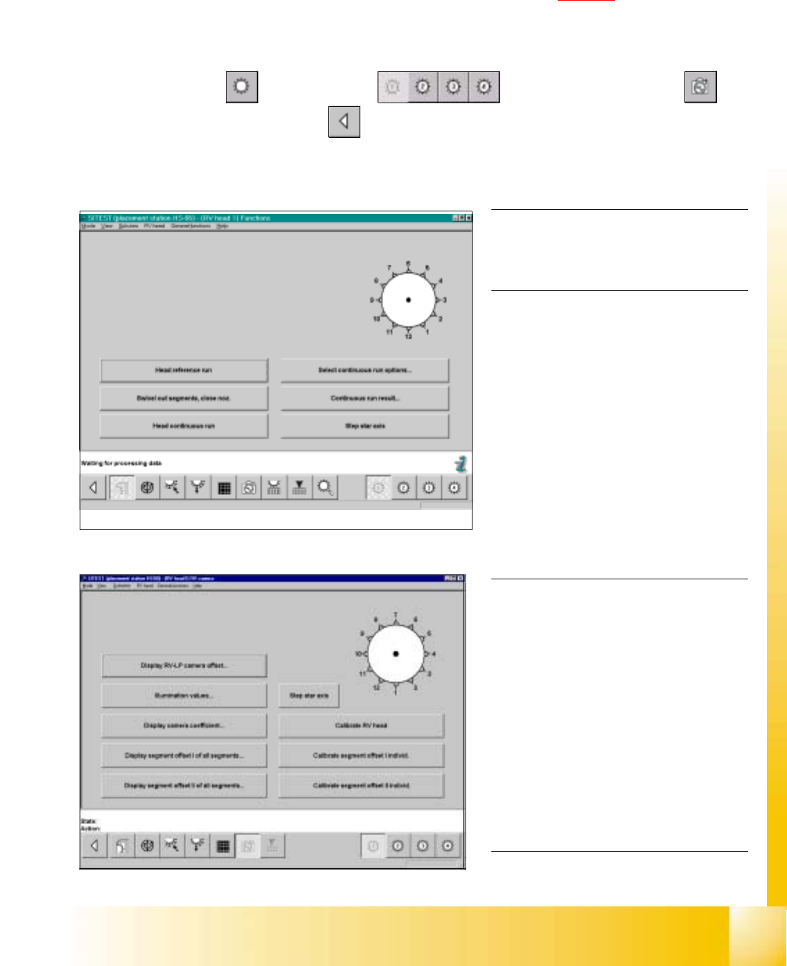
fig 7.3 - 3 Display "Functions of C&P Head"
0
fig 7.3 - 4 Display "C&P Head, C&P camera"
NOTE
Repeat these instructions in order to
calibrate the C&P Heads 2, 3 and 4. 0
For the calibration follow these steps: 0
– Calibration of the PCB - camera
– Calibration of the C&P - camera
– Determination of the segment offsets I
for all 12 segments
– Determination of the segment offsets II
for all 12 segments and the C&P
PCB camera offset, relating to
segment I.
NOTE
With the help of the function "Display
camera coefficient", the determined val-
ues can be displayed after you finished
calibration.
Segment offset I: No deviation > 120 mm
between the individual segments and no
value for a single segment > 450 mm
allowed!
Segment offset II: The value for segment 1
is always 0. 0
7.3.2 Calibration of the Collect & Place Head
Example: C&P Head 1 7
7
à Insert the calibration tool into the "calibration bag" in placement area. (See fig 7.1 - 1).
à Place 12 nozzles, type 956 on the star.
SITEST: 7
à Select "C&P Heads" ==> "C&P Head 1" ==> "C&P Head and camera" ==>
"Calibrate RV head" ==> "Main view" ==> "Settings" ==> "Save machine data".