HS50_advance_level 1_20200522_221201 (1).pdf - 第235页
Studen t Guide HS-50 A dvanced I 06/200 2 Edition 7 Calibration 5 0 fig 7.3 - 3 Di spla y "Fu nc tio ns of C& P He ad" 0 fig 7 .3 - 4 Disp lay "C &P H ead , C&P camera " NOTE Repeat these …
06/2002 Edition Student Guide HS-50 Advanced I
7 Calibration
4
0
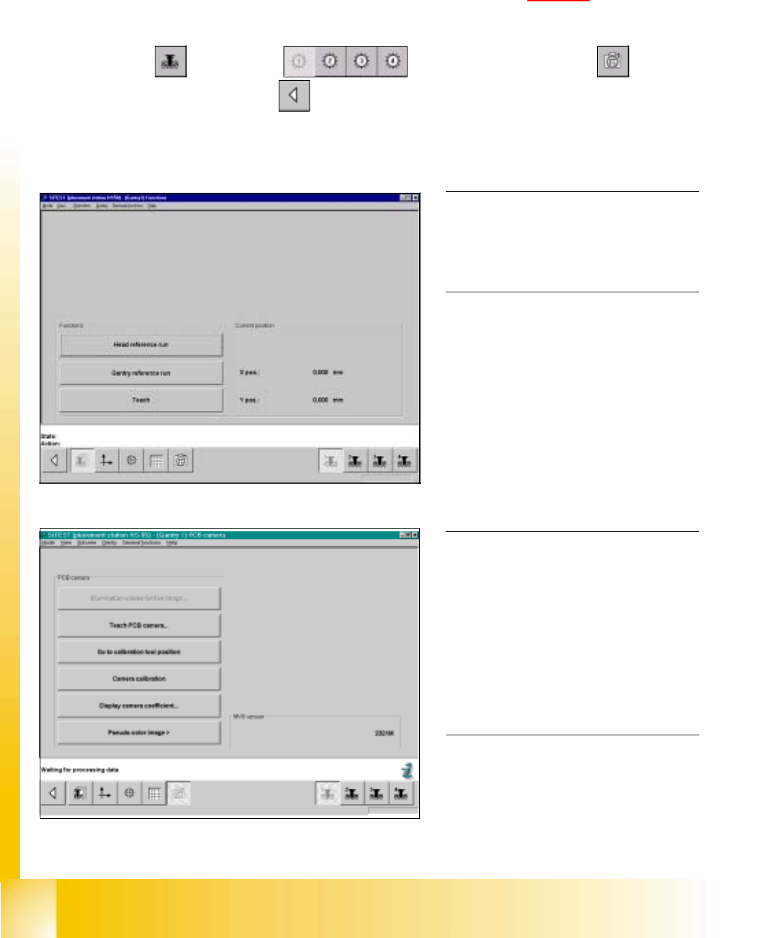
fig 7.3 - 1 Display: "Gantry functions"
0
fig 7.3 - 2 Display "PCB camera functions"
7.3 Single calibration steps
7.3.1 Calibration of PCB - Camera
Example: PCB - camera, gantry 1 7
7
à Insert the calibration tool into the "calibration bag " in placement area 1. (See fig 7.1 - 1).
SITEST: 7
à Select "Gantry" ==> "Gantry 1" ==> "PCB - camera functions" ==>
"Calibrate camera" ==> "Main view" ==> "Settings" ==> "Save machine data".
NOTE
Repeat these instructions in order to
calibrate the PCB - cameras of gantries
2, 3 and 4. 0
0
0
0
0
0
0
0
0
0
0
0
0
NOTE
With the help of the function "Display
camera coefficient", the determined
values can be displayed after you finished
calibration.
The value under "Angle [1 / 100°] must not
exceed 100. 0
Student Guide HS-50 Advanced I 06/2002 Edition
7 Calibration
5
0
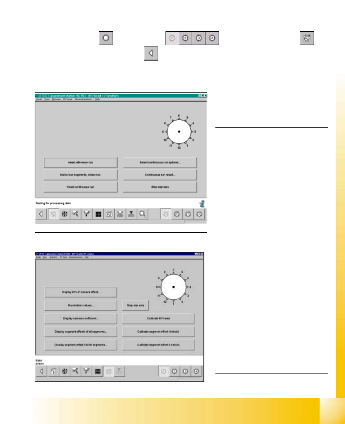
fig 7.3 - 3 Display "Functions of C&P Head"
0
fig 7.3 - 4 Display "C&P Head, C&P camera"
NOTE
Repeat these instructions in order to
calibrate the C&P Heads 2, 3 and 4. 0
For the calibration follow these steps: 0
– Calibration of the PCB - camera
– Calibration of the C&P - camera
– Determination of the segment offsets I
for all 12 segments
– Determination of the segment offsets II
for all 12 segments and the C&P
PCB camera offset, relating to
segment I.
NOTE
With the help of the function "Display
camera coefficient", the determined val-
ues can be displayed after you finished
calibration.
Segment offset I: No deviation > 120 mm
between the individual segments and no
value for a single segment > 450 mm
allowed!
Segment offset II: The value for segment 1
is always 0. 0
7.3.2 Calibration of the Collect & Place Head
Example: C&P Head 1 7
7
à Insert the calibration tool into the "calibration bag" in placement area. (See fig 7.1 - 1).
à Place 12 nozzles, type 956 on the star.
SITEST: 7
à Select "C&P Heads" ==> "C&P Head 1" ==> "C&P Head and camera" ==>
"Calibrate RV head" ==> "Main view" ==> "Settings" ==> "Save machine data".
06/2002 Edition Student Guide HS-50 Advanced I
7 Calibration
6
0
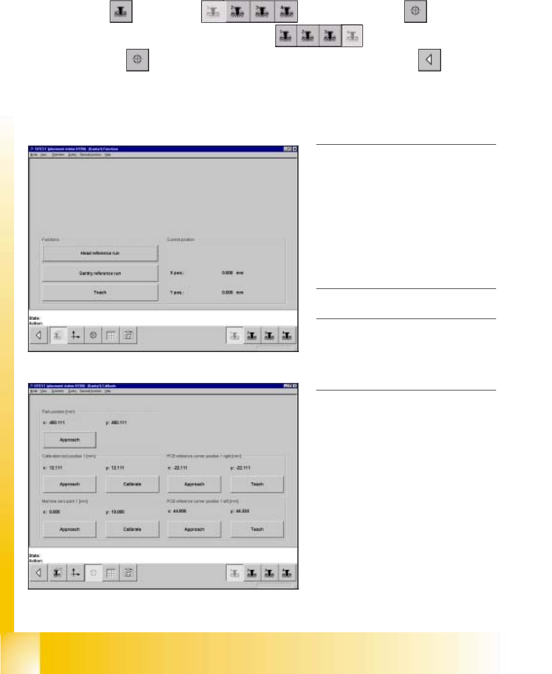
fig 7.3 - 5 Display "Gantry functions"
0
fig 7.3 - 6 Display "Calibration of position"
7.3.3 Calibration of Machine Zero Point
Example: Placement area 1. 7
SITEST: 7
à Select "Gantry" ==> "Gantry 1" ==> "Calibrate position" ==>
"Calibrate (field "Machine zero point")" ==> "Gantry 4" ==>
"Calibrate position" ==> "Calibrate (field "Machine zero point 1")" ==> "Main view" ==>
"Settings" ==> "Save machine data".
NOTE
Make sure that all calibration data for the
C&P camera, the segment offset II (C&P -
PCB camera offset) and the PCB camera
have been determined.
The calibration of the machine zero point
must be performed with both gantries
each in placement area 1 or 2,
respectively. 0
NOTE
Proceed the same way with gantries 2 and
3, in order to determine the machine zero
point in placement area 2. 0