HS50_advance_level 1_20200522_221201 (1).pdf - 第238页
06/2002 E dition Studen t Guide H S-50 Advance d I 7 Calibr ation 8 0 fig 7.3 - 9 D is play "Ca lib r a tio n of no zz le Ch an ger " 0 0 7.3.5 Cal ibration Co llect & Place H ead No zzle Changer 7. 3.5. 1 …
Student Guide HS-50 Advanced I 06/2002 Edition
7 Calibration
7
0
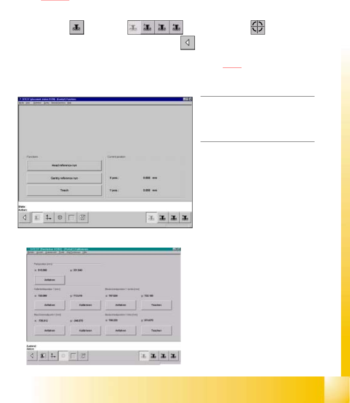
fig 7.3 - 7 Display "Gantry functions"
0
fig 7.3 - 8 Calibratiopn of position
7.3.4 Calibration of Calibration Position
Example: Placement area 1. 7
7
à Insert the calibration tool in to the "calibration bag 1" in placement area 1.
(See
fig 7.1 - 1).
SITEST: 7
à Select "Gantry" ==> "Gantry 1" ==> "Calibrate position" ==>
"Calibrate (field "calibration position 1")"==> "Main view" ==> "Settings" ==> "Save machine data".
à Proceed under section "Calibration of the Pick-Up Height". (See section 7.3.5.3).
NOTE
Proceed the same way with gantry 2, in
order to determine the calibration position
in placement area 2. 0
06/2002 Edition Student Guide HS-50 Advanced I
7 Calibration
8
0
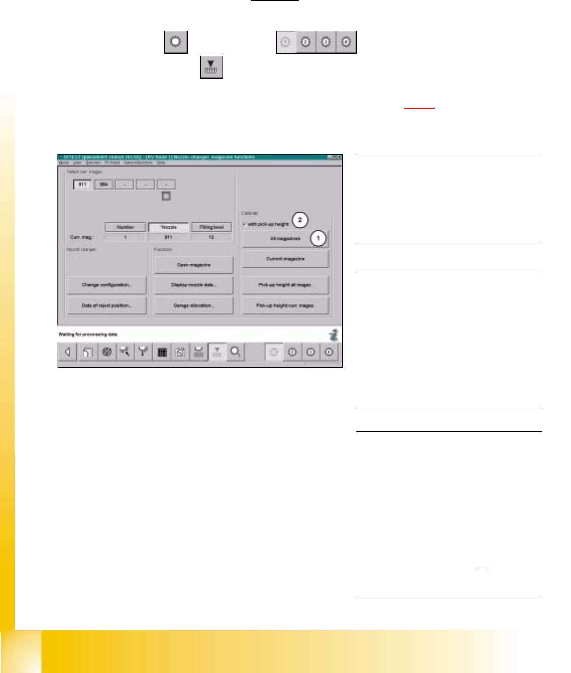
fig 7.3 - 9 Display "Calibration of nozzle Changer"
0
0
7.3.5 Calibration Collect & Place Head Nozzle Changer
7.3.5.1 Complete Calibration
Example: Nozzle changer for C&P Head 1, completely supplied with all 5 or 10 magazines. 7
SITEST: 7
à Select "C&P Heads" ==> "C&P Head 1" ==>
"C&P Head nozzle changer" ==> "All magazines (1)" (with pick up height (2)).
à Have you deactivate the button "with Pick-Up Height" Proceed see section 7.3.5.3).
NOTE
Make sure that the calibration data for the
PCB camera, the segment offset II (C&P
PCB camera offset) and the machine zero
point have been determined already. 0
NOTE
A nozzle changer contains 5 magazines
maximum, with 12 nozzle garages each.
For every single C&P Head, 2 nozzle
changers may be installed. During
calibration these will be handled like one
single nozzle changer with 10 maga-
zines. 0
NOTE
The function "Complete calibration" is
used, if the nozzle changer is completely
loaded with all 5 or 10 magazines.
All 12 nozzles must be on the C&P Head.
With the help of the function "Calibrate
current magazine", x- and y-values must
be individually determined for each
magazine if the changer is not
completely
loaded. 0
Student Guide HS-50 Advanced I 06/2002 Edition
7 Calibration
9
0
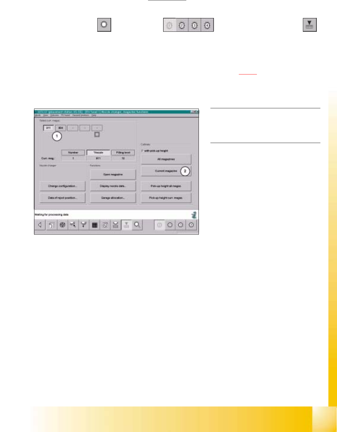
fig 7.3 - 10 Display "C&P Head nozzle changer"
0
0
0
NOTE
The pick-up height must be determined for
each magazine. 0
7.3.5.2 Calibration of the Current Magazine
Example: Nozzle changer for C&P Head 1, not completely loaded with all magazines. 7
SITEST: 7
à Select "C&P Heads" ==> "C&P Head 1" ==> "C&P Head nozzle changer"
==> select the current "Magazine number...(1)" ==>Calibrate "Current magazine (2) ".
à Repeat these instructions with all magazines.
à Have you deactivate the button "with Pick-Up Height" Proceed see section 7.3.5.3).