HS50_advance_level 1_20200522_221201 (1).pdf - 第240页
06/2002 E dition Studen t Guide H S-50 Advance d I 7 Calibr ation 10 0 f ig 7. 3 - 1 1 Di sp lay "C &P H ead n ozz le ch ang er" 0 0 0 0 0 0 0 0 0 0 0 0 0 0 0 0 7.3.5.3 Calibr ation of P ick-Up Height à A s…
Student Guide HS-50 Advanced I 06/2002 Edition
7 Calibration
9
0
fig 7.3 - 10 Display "C&P Head nozzle changer"
0
0
0
NOTE
The pick-up height must be determined for
each magazine. 0
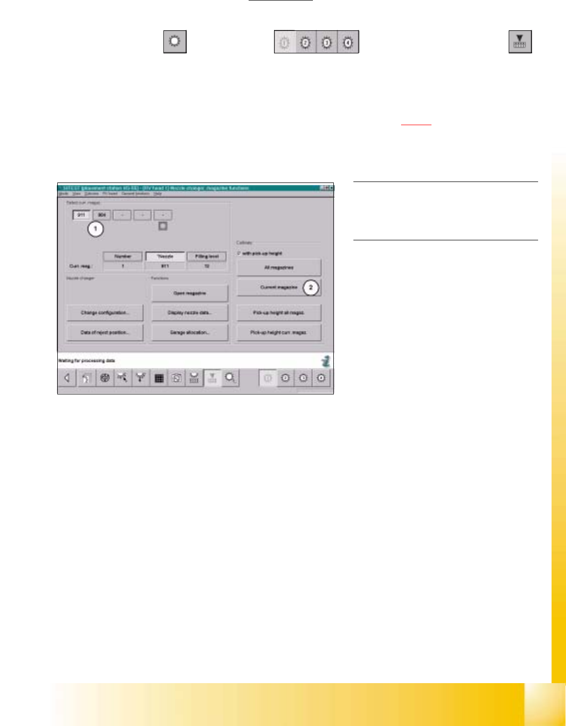
7.3.5.2 Calibration of the Current Magazine
Example: Nozzle changer for C&P Head 1, not completely loaded with all magazines. 7
SITEST: 7
à Select "C&P Heads" ==> "C&P Head 1" ==> "C&P Head nozzle changer"
==> select the current "Magazine number...(1)" ==>Calibrate "Current magazine (2) ".
à Repeat these instructions with all magazines.
à Have you deactivate the button "with Pick-Up Height" Proceed see section 7.3.5.3).
06/2002 Edition Student Guide HS-50 Advanced I
7 Calibration
10
0
fig 7.3 - 11 Display "C&P Head nozzle changer"
0
0
0
0
0
0
0
0
0
0
0
0
0
0
0
0
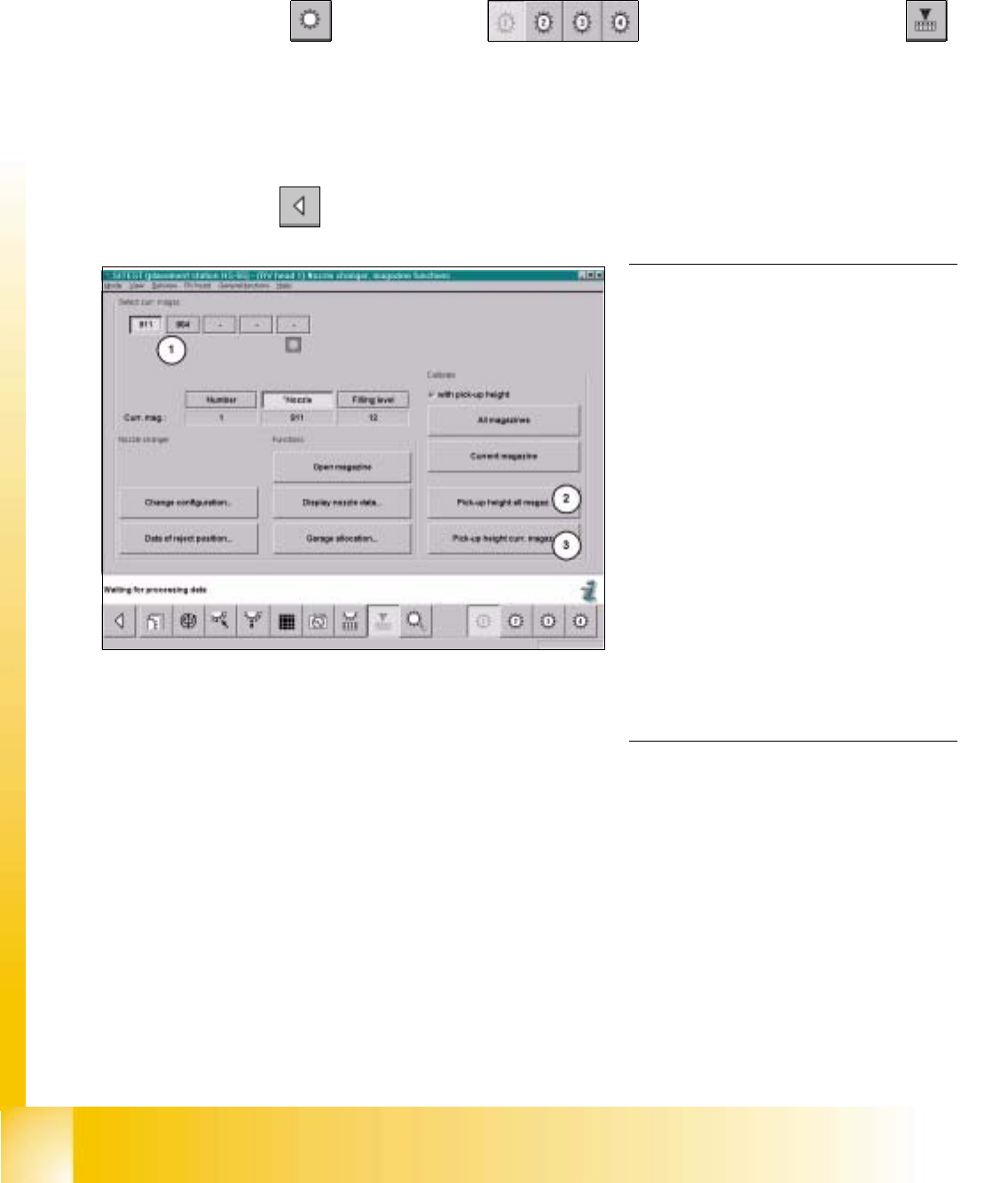
7.3.5.3 Calibration of Pick-Up Height
à Ascertain, that there is a nozzle on the lower segment, and that all garages selected below, are empty.
SITEST: 7
à Select "C&P Heads" ==> "C&P Head 1" ==> "C&P Head nozzle changer"
==> select the current "Magazine number...(1)" ==>Calibrate "Pick-up height current magazine (3) " or
"Pick-up height all magazines (2) ".
à Repeat this procedure for all magazines, if it necessary.
à Select "Main View" ==> "Settings" ==> "Save machine data".
NOTE
Each individually determined pick-up
height (z-position) will be displayed in a di-
alogue box, after the calibration.
The z-position of the reject container will
be calculated from the pick-up height
determined for the last magazine.
If you want to test if the calibration was
successful, you should always FIRST
save the determined calibration data
("Main view" ==> "Settings" ==> "Save
machine data"). After saving the data,
return to the display "C&P Head nozzle
changer".
With the help of the functions "Place / Pick-
up" you can test the calibration result. 0
Student Guide HS-50 Advanced I 06/2002 Edition
7 Calibration
11
0
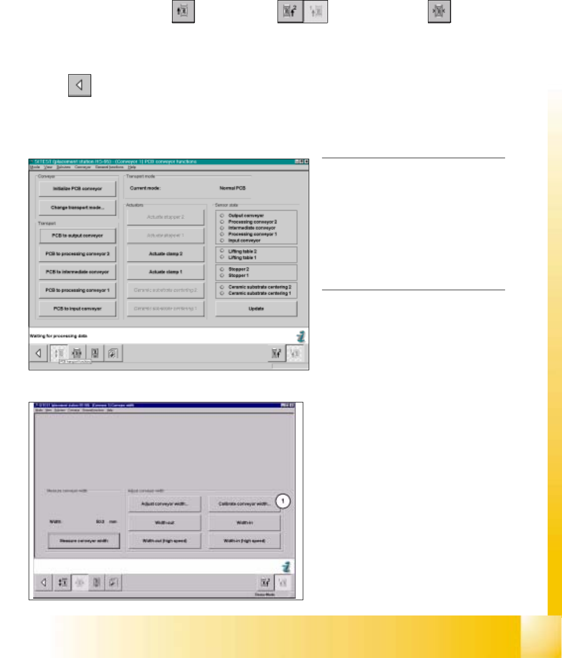
fig 7.3 - 12 Display: "Conveyor functions"
0
fig 7.3 - 13 Display: "Conveyor width"
NOTE
Using the functions of the width adjust-
ment, no PCB may be in the conveyor and
the lifting tables must be down.
If the system has a dual conveyor in-
stalled, the conveyor width for conveyor 2
(left - hand conveyor) must get calibrated
as described above. 0
7.3.6 Calibration of Conveyor Width
Example: Conveyor 1 (= right hand conveyor). 7
SITEST: 7
à Select "Placement conveyor" ==> "Conveyor 1" ==> "Conveyor width" ==>
"Calibrate conveyor width (1) " ==> "Insert a PCB with 100 mm of width into conveyor 1" ==> "With the help
of the functions "wider" / "narrower" (in the dialogue box), adjust to the width of the PCB" ==> "OK" ==>"Main
view" ==> "Settings" ==> "Save machine data".