HS50_advance_level 1_20200522_221201 (1).pdf - 第242页
06/2002 E dition Studen t Guide H S-50 Advance d I 7 Calibr ation 12 0 f ig 7. 3 - 14 Fix ed PCB c orn er f ig 7. 3 - 15 F ixed PC B c orn er, PCB ca m era 7.3.7 Measu r i n g the Fixe d PC B corn er Exam ple: Placement …
Student Guide HS-50 Advanced I 06/2002 Edition
7 Calibration
11
0
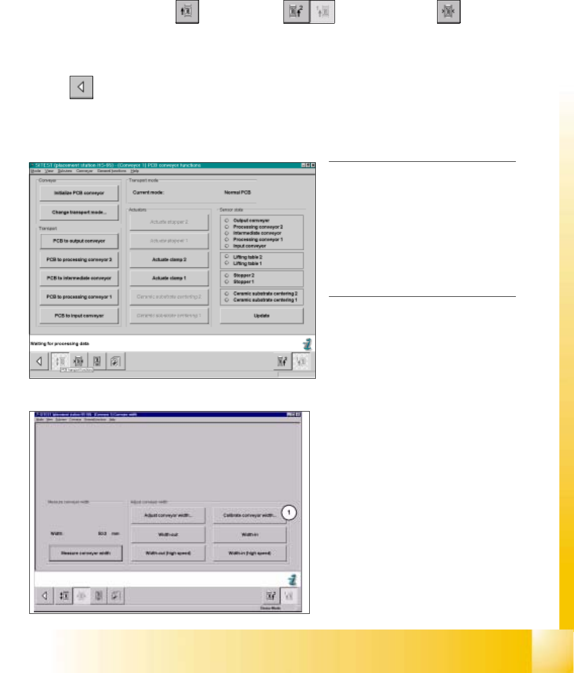
fig 7.3 - 12 Display: "Conveyor functions"
0
fig 7.3 - 13 Display: "Conveyor width"
NOTE
Using the functions of the width adjust-
ment, no PCB may be in the conveyor and
the lifting tables must be down.
If the system has a dual conveyor in-
stalled, the conveyor width for conveyor 2
(left - hand conveyor) must get calibrated
as described above. 0
7.3.6 Calibration of Conveyor Width
Example: Conveyor 1 (= right hand conveyor). 7
SITEST: 7
à Select "Placement conveyor" ==> "Conveyor 1" ==> "Conveyor width" ==>
"Calibrate conveyor width (1) " ==> "Insert a PCB with 100 mm of width into conveyor 1" ==> "With the help
of the functions "wider" / "narrower" (in the dialogue box), adjust to the width of the PCB" ==> "OK" ==>"Main
view" ==> "Settings" ==> "Save machine data".
06/2002 Edition Student Guide HS-50 Advanced I
7 Calibration
12
0
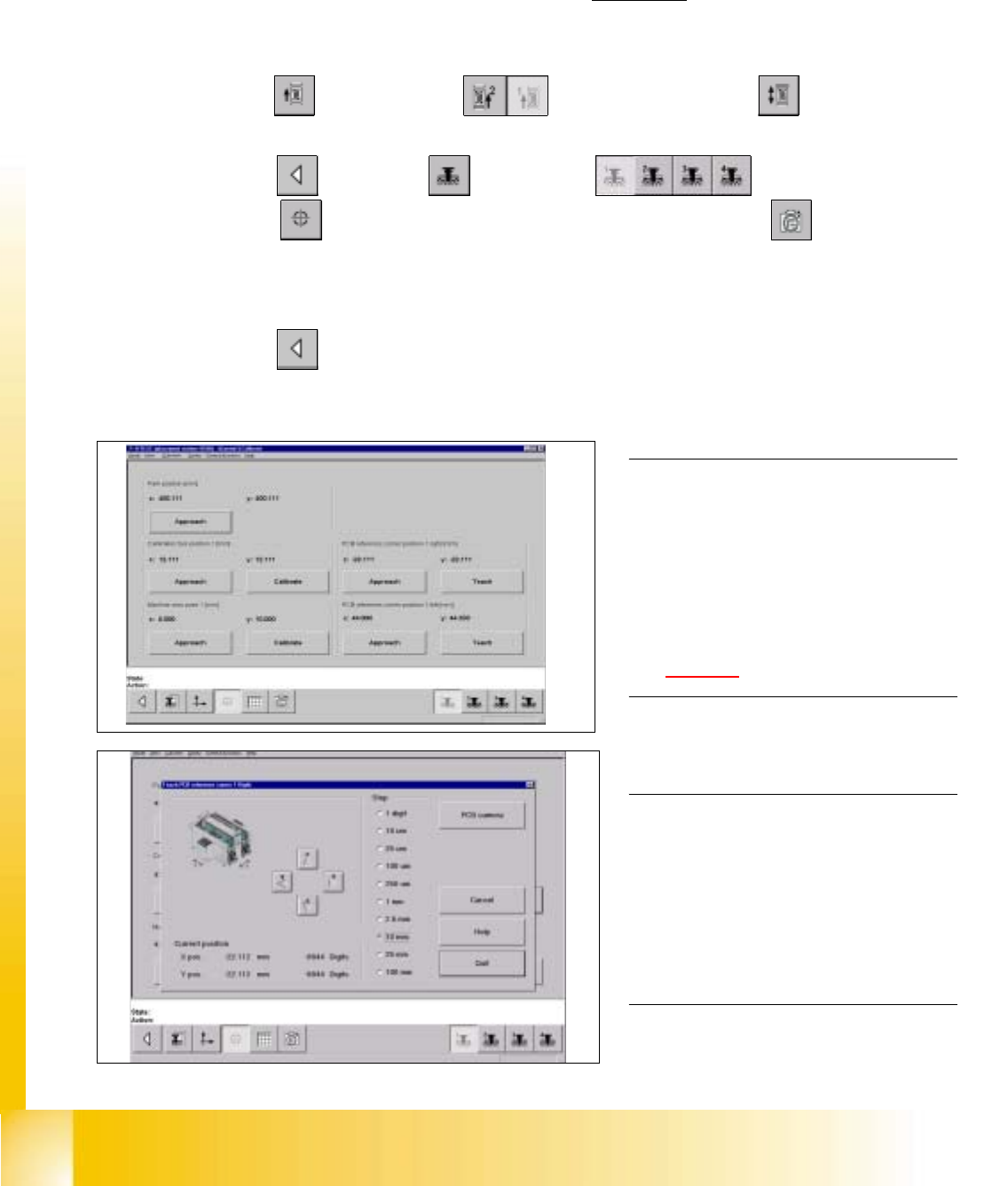
fig 7.3 - 14 Fixed PCB corner
fig 7.3 - 15 Fixed PCB corner, PCB camera
7.3.7 Measuring the Fixed PCB corner
Example: Placement area 1 , conveyor of the right hand side (conveyor 1). 7
7
à With the help of the conveyor functions, move a PCB with a light surface into the processing conveyor 1, in
which you wish to measure the position of the fixed PCB corner.
SITEST: 7
à Select "Conveyor" ==> "Conveyor 1" ==> "Conveyor functions" .
à With the help of the conveyor functions, move the PCB into placement area 1.
à Select "Main view" ==> "Gantry" ==> "Gantry 1" ==>
"Calibrate position" ==> "Teach (field 1, right hand side)" ==> "PCB camera" .
à With the help of the cursor buttons, teach the position of the fixed PCB corner.
à Select ESC accept the position with "End".
à Select "Main view" ==> "Settings" ==> "Save machine data".
NOTE
Make sure that the calibration data for the
PCB camera, the segment offset II (C&P -
PCB camera offset) and the machine zero
point have been determined already.
The position of the fixed PCB corners
varies according to conveyor model.
See fig 7.1 - 1. 0
0
0
NOTE
To measure the placement position in
placement area 2, follow the instructions
as detailed above, for gantry 2 as well.
If a dual conveyor is installed, the fixed
PCB corners of the left hand conveyor
(conveyor 2) must be measured as well. 0
Student Guide HS-50 Advanced I 06/2002 Edition
7 Calibration
13
0
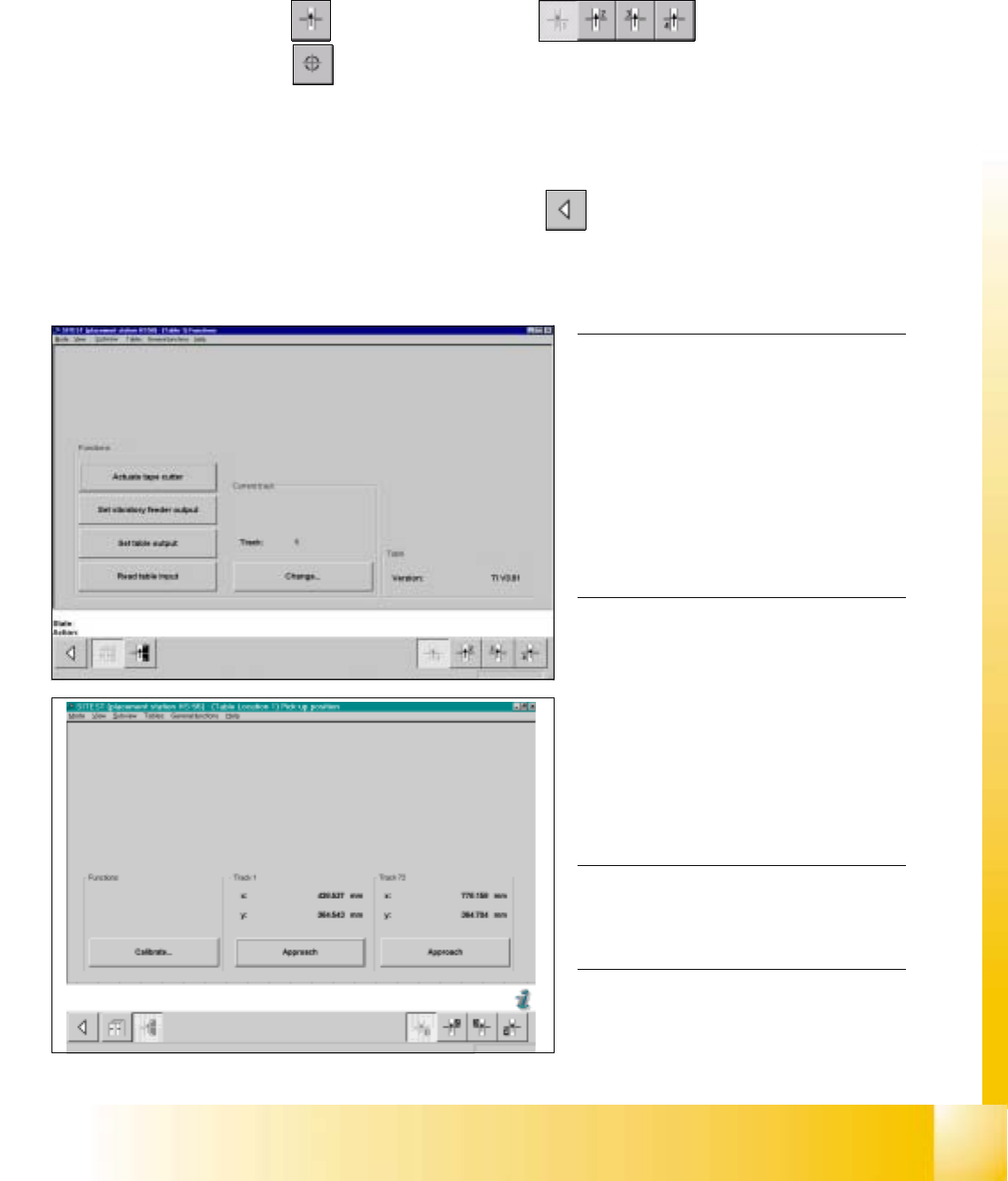
fig 7.3 - 16 Display: "Functions of the component table"
fig 7.3 - 17 Display: "Pick-up position"
NOTE
Make sure that the calibration data for the
PCB camera, the segment offset II (C&P -
PCB camera offset) and the machine zero
point have been determined already.
Before you use the gauge, make sure that
the appropriate component table under
the gauge is free of unevenness and dirt.0
0
0
0
0
0
0
0
0
0
0
NOTE
Measuring the component tables 2, 3 and
4, proceed the same way. 0
0
0
0
0
7.3.8 Calibration of the Component Table
Example: Component table 1 7
SITEST: 7
à Select "Component tables" ==> "Component table 1" ==>
"Calibrate pick-up position" .
à Set the gauge to track1 of the component table 1.
à Select "Calibrate (field "track1") ==> "OK".
à Set the gauge to track 72 of the component table 1.
à Select "Calibrate (field "track 72") ==> "OK" ==> "Main View" ==> "Settings" ==> "Save machine data".