HS50_advance_level 1_20200522_221201 (1).pdf - 第250页
06/2002 E dition Studen t Guide H S-50 Advance d I 20 2 © PL EA 1 V GC Train ing Ver s i on Dec / 0 0 Ca libr ation of S IP LA C E HS- 50 Calibration Steps The differe nt calibration ste ps are integr ated in the SITEST …

Student Guide HS-50 Advanced I 06/2002 Edition
19
7.4 Machine Offsets and their interrelationships
1
©
PL EA 1 V GC Training
Version Dec / 00
Calibration of SIPLACE HS-50
Whenever mechanical repair work has been done:
Ø for proper operation of the machine mechanical
adjustments are necessary and
Ø for the placement accuracy within our
specification some functions must been
meassured / calibrated.
06/2002 Edition Student Guide HS-50 Advanced I
20
2
©
PL EA 1 V GC Training
Version Dec / 00
Calibration of SIPLACE HS-50
Calibration Steps
The different calibration steps are integrated in the SITEST test software.
With „calibrate heads and cameras“ the following sequence is executed automatically
Ø calibrate the PCB-camera
Ø calibrate the component-camera
Ø execute the segment offset I (above)
Ø execute the segment offset II (below) and the camera camera offset
Ø calibrate machine zero point
Ø calibrate nozzle changer
Ø calibrate the P&P (IC)-camera with P&P head the Flip-chip-camera
Additionally manual work
Ø calibrate the pick up height of nozzles
Ø calibrate coordinates at the PCB transport
Ø calibrate component table positions
Ø calibrate the coplanarity module (option)
Before starting calibration
Ø program Star axis zero point correction
3
©
PL EA 1 V GC Training
Version Dec / 00
Calibration of SIPLACE HS-50
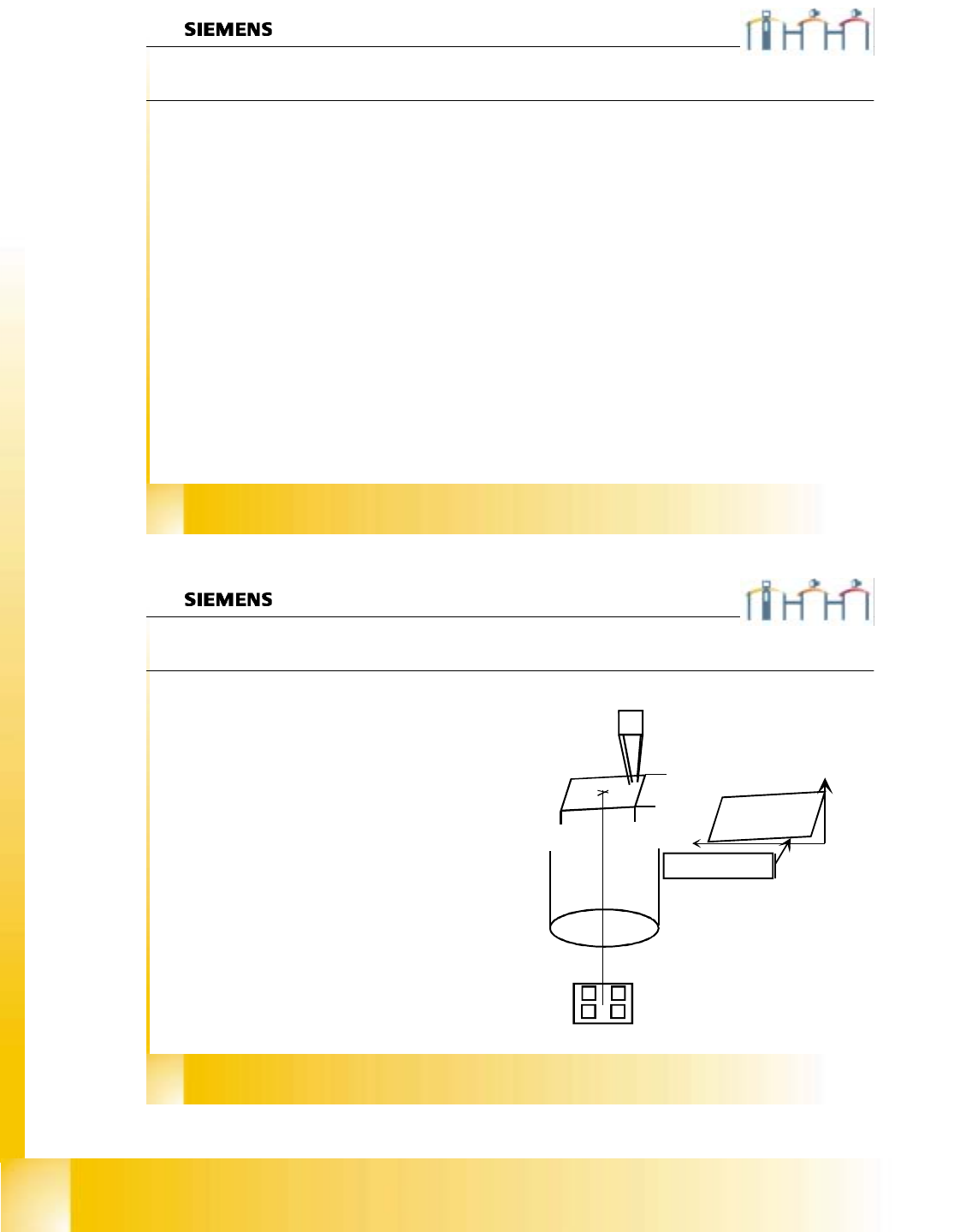
Calibrate PCB camera
In this menu we determine:
Ø the mechanical Pixel size of the CCD-sensor
in µm.
This is calculated with the calibration
factors „Kalibrierfaktoren“ AX/BX/CX ...
Saved in REAL.MA
XU_Pixel / YU_Pixel. (in 11500nm)
Ø the camera center pixel.
Ø the angle of the CCD-Sensor according the
machine coordinate system.
Saved in REAL.MA
“Kamera_offset_Winkel“
Ø the camera offset is done with segment offset
above (II)
CCD Sensor angle to the
machine coordinate system
11,5 µm
11,5 µm
5800µm
5800µm
Student Guide HS-50 Advanced I 06/2002 Edition
21
4
©
PL EA 1 V GC Training
Version Dec / 00
Calibration of SIPLACE HS-50
Calibration of the component camera
With this menu we determine:
Ø the mechanical Pixel size of the CCD-sensor in
µm.
This is calculated with the calibration factors
„Kalibrierfaktoren“ AX/BX/CX ...
Saved in REAL.MA
XU_Pixel / YU_Pixel. (in 24000 nm)
Ø the camera center pixel.
Ø the angle of the CCD-Sensor according the
turning level of the Placement Star.
Saved in REAL.MA „Kamera_offset_Winkel“
Ø the camera offset is set to Zero (because the
camera center is the reference for calibrations).
Saved in REAL.MA
„Kamera_offset_X“/„Kamera_offset_Y“
49,2 µm
49,2 µm
24000µm
24000µm
CCD Sensor angle
refering to the turning
level of the
placement star
5
©
PL EA 1 V GC Training
Version Dec / 00
Calibration of SIPLACE HS-50
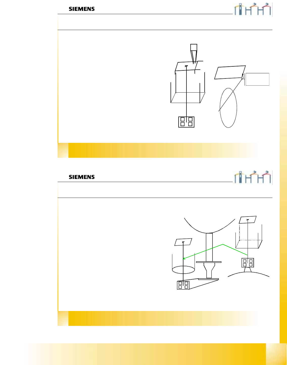
Segment offset II
The sequence at segment offset bottom / II is:
Ø We center the actual calibration tool position
with the PCB camera. Then we pick it up
and center it optically in the component
camera. The moving distance and the com-
ponent offset is taken for the result.
Ø With segment number 1 we calculate the
distance between the two camera centers;
called (RV-head) camera (PCB) camera
offset. This is saved in REAL.MA in the data
bloc of the PCB camera.
KAMERA_OFFSET_X
KAMERA_OFFSET_Y.
Ø All other segments get an OFFSET to this
segment 1;called segment offset II of this
segment .
Ø This is saved in PIP_OFF.MA file