HS50_advance_level 1_20200522_221201 (1).pdf - 第253页
Studen t Guide HS-50 A dvanced I 06/200 2 Edition 23 8 © PL EA 1 V GC Tra i ni ng Version Dec / 0 0 Cal ibr ation of SI PL ACE H S-5 0 Machine zero p oint Ø With the PCB c amer a we c enter the hole dr ille d o n th e f …
06/2002 Edition Student Guide HS-50 Advanced I
22
6
©
PL EA 1 V GC Training
Version Dec / 00
Calibration of SIPLACE HS-50
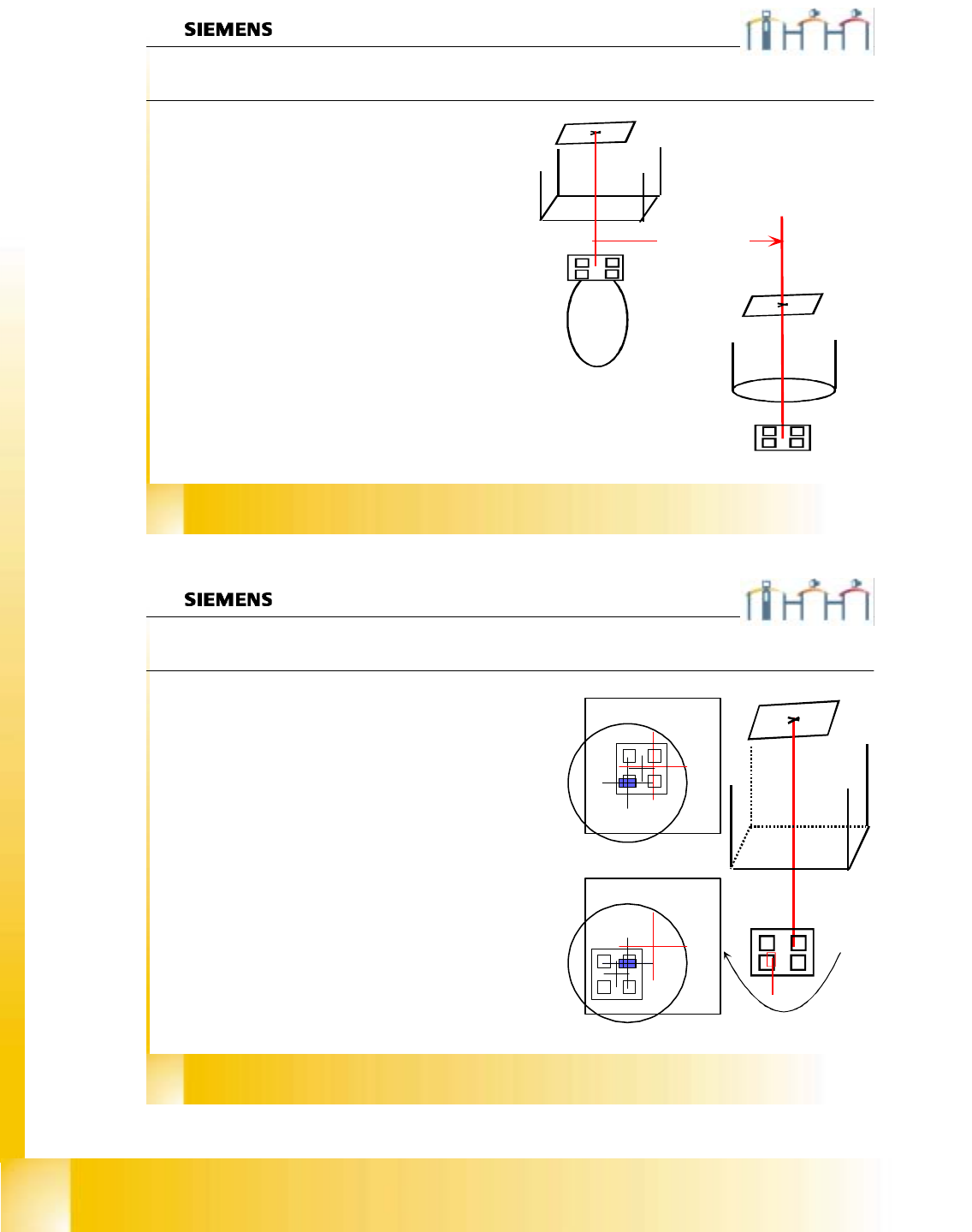
Pcb camera - component camera offset
With segment number 1 we calibrate the distance
between component -and PCB-camera center;
called (RV-head) camera - (PCB) camera offset.
The machine center optically PCB camera the
calibration tool in the “tool pocket”. This
calibration tool is picked up with segment number
1 and optically centered in (RV) component
camera.
The travel distance of PCB camera from the
measured tool position to the measured actual tool
center position is measured.
This measured distance is set for the camera -
camera distance. There is not maximum limit set
for.
The component camera center is set for the
reference position.
OFFSET of the
cameras
7
©
PL EA 1 V GC Training
Version Dec / 00
Calibration of SIPLACE HS-50
Segment offset I
0°
180°
With this menu we determine:
Ø the mechanical distance between center of the
component camera to the center of the turning axis
of the segment in µm.
This is calculated with a 180° turning of the
calibration tool on the nozzle.
Saved in PIP_OFF.MA.
Ø Picture 1 segment with calibration tool in 0° under
the camera. DP station turn than in 90° steps and
on each angle this measurement is done.
Ø First measurement results from 0° and 180° taken
to calculate turning axis.
The plausibility check is done with
the results from 90° and 270°.
Ø Picture 2 segment with calibration tool in 180°
under the camera.
Student Guide HS-50 Advanced I 06/2002 Edition
23
8
©
PL EA 1 V GC Training
Version Dec / 00
Calibration of SIPLACE HS-50
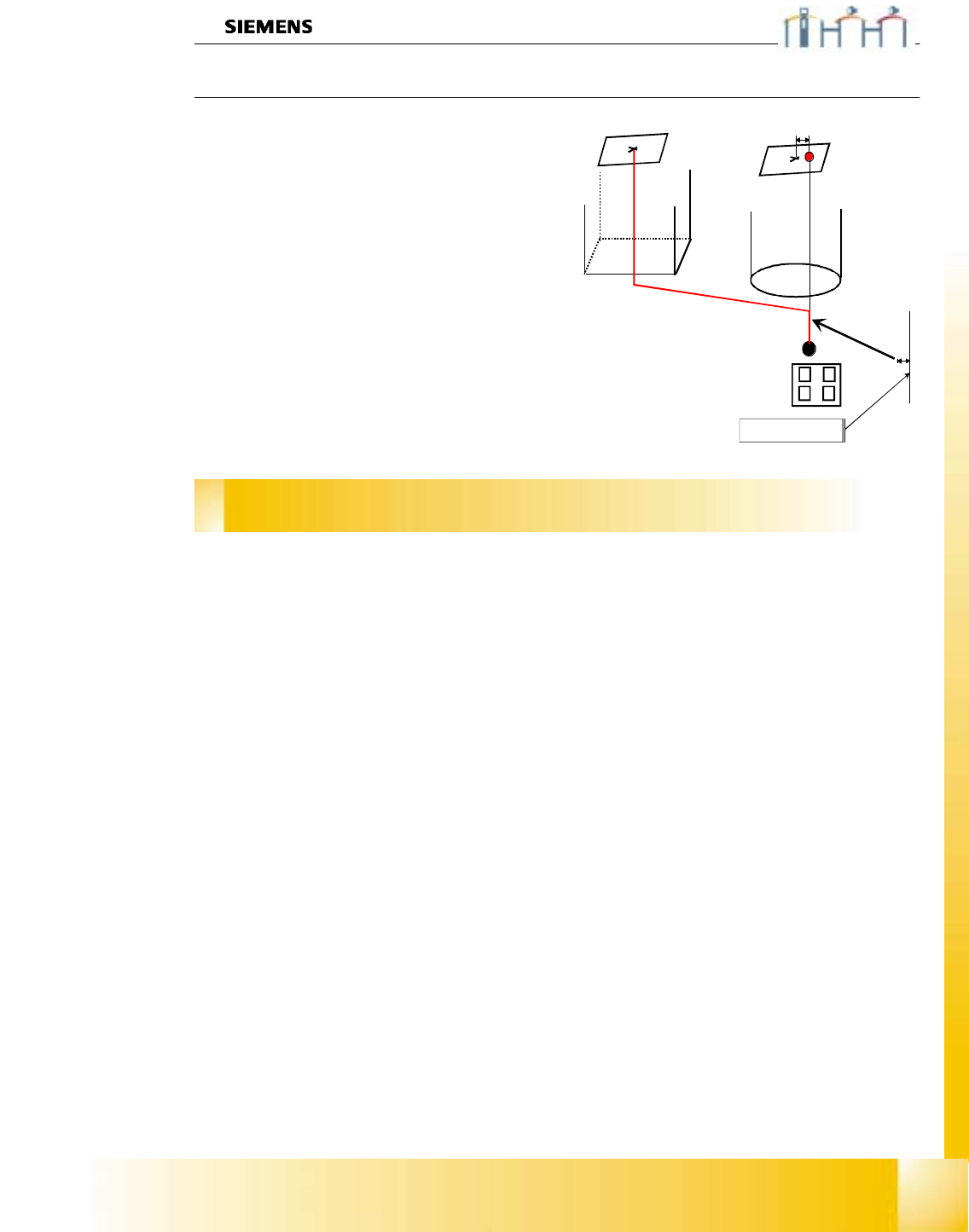
Machine zero point
Ø With the PCB camera we center the hole
drilled on the fixed transport rail. This position
has fixed X&Y coordinates.
Ø At this mechanical fixed position we calibrate
all gantry axes of 1 placement group area
(maximum is 2 gantries).
Ø With the calculation we consider the actual
valid camera - camera offset.
Ø The Zero point corrections of all gantry axes
are changed about the measured offset.
Ø When the center of the component camera is
exactly above the drilled hole. The axis position
counter shows you the value of
MA_Nullpunkt_X_pg1 /
MA_Nullpunkt_Y_pg1 .
Zero point correction
measured with the PCB camera
fixed distance

06/2002 Edition Student Guide HS-50 Advanced I
24