HS50_advance_level 1_20200522_221201 (1).pdf - 第306页
\ SP4_Marke1_Pos_y_soll \ 1545750, Y-coordinate feeder table 4 track 1 Xnominal 4 2 \ SP_Offset_Marke_X \ 31600, this is the X-dimension of one feeder position \ SP_Offset_Marke_Y \ 0, Y-coordinate of the fiducial define…
\ ParkPosition_Offset_y \
30000,
offset from the SW-Limits to operate the gantries in a save way with SITEST
\ Minimaler_Kopfabstand_y \
350000,
Minimal sleeve- sleeve distance of the placement head on the gantries
\ Breitenverstellung
_Referenzwert_1 \
750037,
Width adjustment bero position for right Transport, calibrated with gantry 2 at a
100mm wide adjusted Transport rail
\ Breiten
verstellung_Referenzwert_2 \
1001776,
Width adjustment bero position for left Transport, calibrated with gantry 2 at a
100mm wide adjusted Transport rail
\ Breitenverstellung_Offset \
171133,
\ Offset _z0_Transp_Unterkante \
7000,
coordinate to calculate the PCB-bottomside and following the placement height
\ Delta
_Best_Nest_x_vorne_rechts \
787500,
BB1 Standard-X-coordinate PCB-reference corner in the right Transport track of a
right double or single transport
\ Delta
_Best_Nest_y_vorne_rechts \
722125,
BB1 Standard-Y-coordinate PCB-reference corner in the right Transport track of a
right double or single transport
\ Delta _Best_Nest_x_vorne_links
\
787257,
BB1 Standard-X-coordinate PCB-reference corner in the left Transport track of a
right double transport
\ Delta
_Best_Nest_y_vorne_links \
973670,
BB1 Standard-Y-coordinate PCB-reference corner in the left Transport track of a
right double transport
\ Delta
_Best_Nest_x_hinten_rechts \
1624125,
BB2 Standard-X-coordinate PCB-reference corner in the right Transport track of a
right double or single transport
\ Delta
_Best_Nest_y_hinten_rechts \
722320,
BB2 Standard-Y-coordinate PCB-reference corner in the right Transport track of a
right double or single transport
\ Delta
_Best_Nest_x_hinten_links \
1623415,
BB2 Standard-X-coordinate PCB-reference corner in the left Transport track of a
right double transport
\ Delta
_Best_Nest_y_hinten_links \
973925,
BB2 Standard-Y-coordinate PCB-reference corner in the left Transport track of a
right double transport
\ Koplanaritaet_1_x
\
0,
not used in a 503.XX SW machine type
\ Koplanaritaet_1_y \
0,
not used in a 503.XX SW machine type
\ Koplanaritaet_1_z \
0,
not used in a 503.XX SW machine type
\ Koplanaritaet_2_x
\
0,
not used in a 503.XX SW machine type
\ Koplanaritaet_2_y \
0,
not used in a 503.XX SW machine type
\ Koplanaritaet_2_z \
0,
not used in a 503.XX SW machine type
\ IC-Abwurfposition_1_x
\
0,
not used in a 503.XX SW machine type
\ IC-Abwurfposition_1_y
\
0,
not used in a 503.XX SW machine type
\ IC-Abwurfposition_1_z
\
0,
not used in a 503.XX SW machine type
\ IC-Abwurfposition_2_x
\
0,
not used in a 503.XX SW machine type
\ IC-Abwurfposition_2_y
\
0,
not used in a 503.XX SW machine type
\ IC-Abwurfposition_2_z
\
0,
not used in a 503.XX SW machine type
\ SP1_Marke1_Pos_x_soll
\
428950,
nominal value for SITEST to calibrate X-coordinate feeder table 1 track 1
\ SP1_Marke1_Pos_y_soll \
365750,
Y-coordinate feeder table 1 track 1
\ SP2_Marke1_Pos_x_soll \
1266450,
X
-coordinate feeder table 2 track 1. From now only 1 nominal position of a feeder
table is defined. The 2 fiducial is determined with a Matrix.
\ SP2_Marke1_Pos_y_soll \
365750,
Y-coordinate feeder table 2 track 1. From now only 1 nominal position of a feeder
table is defined. The 2 fiducial is determined with a Matrix.
\ SP3_Marke1_Pos_x_soll \
1614050,
X
-coordinate feeder table 3 track 1 Xnominal 31 Note:
NEVER change this nominal coordiates. Sitest use this coordinates to move to the
fiducial for feeder table position calibration. If you change this calibration may work
but the correction factors AX BX...VY are wrong to pick up components from the
feeders!!!
\ SP3_Marke1_Pos_y_soll \
1545750,
Y-coordinate feeder table 3 track 1 Xnominal 3
2
\ SP4_Marke1_Pos_x_soll
\
776550,
X
-coordinate feeder table 4 track 1 Xnominal 41
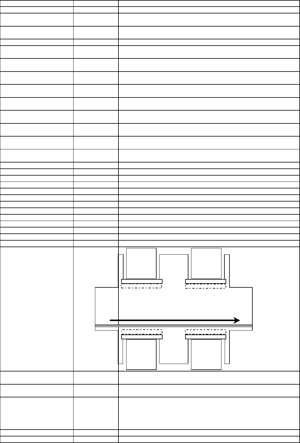
M1 M2
feeder table1
M1 M2
feeder table2
feeder table3
M2 M1
feeder table4
M2 M1
Edition 1.0 2 REAL_MA_e.xls REAL.MA SD EA1 S GC Training
\ SP4_Marke1_Pos_y_soll \
1545750,
Y-coordinate feeder table 4 track 1 Xnominal 4
2
\ SP_Offset_Marke_X \
31600,
this is the X-dimension of one feeder position
\ SP_Offset_Marke_Y \
0,
Y-coordinate of the fiducial define the Y-position of the component table
\ SP1_Korr_AX \
1.000014E+000,
calculation of the real fiducial positions with matrix calculation:
X
12ist = (X11soll+ 11*31600) * AX+Y11soll* BX+VX
\ SP1_Korr_BX \
1.524745E-004,
X
11ist = X11soll * AX+Y11soll* BX+VX
\ SP1_Korr_VX \
-6.189378E+002,
To pick up a comp. the nom.position is taken from feed.setup data file of LC. X-
Feed-ist = Xtrack-soll* AX+Ytrack-soll* BX+VX + Xpickoffset-Feedtype +Xlearn
this calculation is done for each used track in the set up. for the following comp.
tables on each refering comp.table.
\ SP1_Korr_AY \
-1.524745E-004,
Y12ist = (X11soll + 11*31600) * AY+Y11soll* BY+VY
\ SP1_Korr_BY \
1.000014E+000,
Y11ist = X11soll * AY+Y11soll* BY+VY
\ SP1_Korr_VY \
-2.385713E+001,
Y-Feed-ist = Xtrack-soll * AY+Ytrack-soll* BY+VY +Ypickoffset-Feedtype +Ylearn
\ SP2_Korr_AX \
1.000000E+000,
X
22ist = (X21soll +11*31600)* AX+Y21soll* BX+VX
\ SP2_Korr_BX \
0.000000E+000,
X
21ist = X21soll * AX+Y21soll* BX+VX
\ SP2_Korr_VX \
-5.660000E+002,
component pickup coordinate see example calculation on feeder table 1
\ SP2_Korr_AY \
0.000000E+000,
Y22ist = (Y21soll + 11*31600) * AY+Y21soll* BY+VY
\ SP2_Korr_BY \
1.000000E+000,
Y21ist = Y21soll * AY+Y21soll* BY+VY
\ SP2_Korr_VY \
-1.810000E+002,
component pickup coordinate see example calculation on feeder table 1
\ SP3_Korr_AX \
9.999999E-001,
X
32ist = (X31soll -11*31600)* AX+Y31soll* BX+VX
\ SP3_Korr_BX \
-3.452670E-004,
X
31ist = X31soll * AX+Y31soll* BX+VX
\ SP3_Korr_VX \
-1.620737E+001,
component pickup coordinate see example calculation on feeder table 1
\ SP3_Korr_AY \
3.452670E-004,
Y32ist = (Y31soll - 11*31600) * AY+Y31soll* BY+VY
\ SP3_Korr_BY \
9.999999E-001,
Y31ist = Y31soll * AY+Y31soll* BY+VY
\ SP3_Korr_VY \
-5.491860E+002,
component pickup coordinate see example calculation on feeder table 1
\ SP4_Korr_AX \
1.000170E+000,
X
42ist = (X41soll -11*31600)* AX+Y41soll* BX+VX
\ SP4_Korr_BX \
4.315317E-005,
X
41ist = X41soll * AX+Y41soll* BX+VX
\ SP4_Korr_VX \
-7.065124E+002,
component pickup coordinate see example calculation on feeder table 1
\ SP4_Korr_AY \
-4.315317E-005,
Y42ist = (Y41soll - 11*31600) * AY+Y41soll* BY+VY
\ SP4_Korr_BY \
1.000170E+000,
Y41ist = Y41soll * AY+Y41soll* BY+VY
\ SP4_Korr_VY \
-3.418585E+002,
component pickup coordinate see example calculation on feeder table 1
\ Hoehenverm_x_pg1 \
788000,
X
- nozzle length measurement position (height measurment position) for gantry1 and
4. Single- or double transport right side fixed.
\ Hoehenverm_y_pg1 \
713450,
Y-nozzle length measurement position (height measurment position) for gantry1 and
4 at: DT-Rright| DT-Left is around. 1198050
\ Hoehenverm_x_pg2
\
1255000,
X
- nozzle length measurement position for gantry2 and
3
\ Hoehenverm_y_pg2 \
713450,
Y-nozzle length measurement position for gantry 2 and 3 at: DT-Right | DT-Left is
arround 1198050)
\ Kalibrierteilpos_x_pg1
\
720096,
pick up position for calibration tool for for the gantries 1 and 4
\ Kalibrierteilpos_y_pg1 \
713567,
pick up position for calibration tool for for the gantries 1 and 4
\ Kalibrierteilpos_x_pg2
\
1323243,
pick up position for calibration tool for for the gantries 2 and 3
\ Kalibrierteilpos_y_pg2 \
713604,
pick up position for calibration tool for for the gantries 2 and 3
\ MTC1_Marke1_Pos_x_soll \
0,
Only for S25HMX
(MTC for HS 50 not prepared yet)
\ MTC1_Marke1_Pos_y_soll
\
0,
Only for S25HM
X
\ MTC2_Marke1_Pos_x_soll
\
0,
normal Feeder area no MTC to moun
t
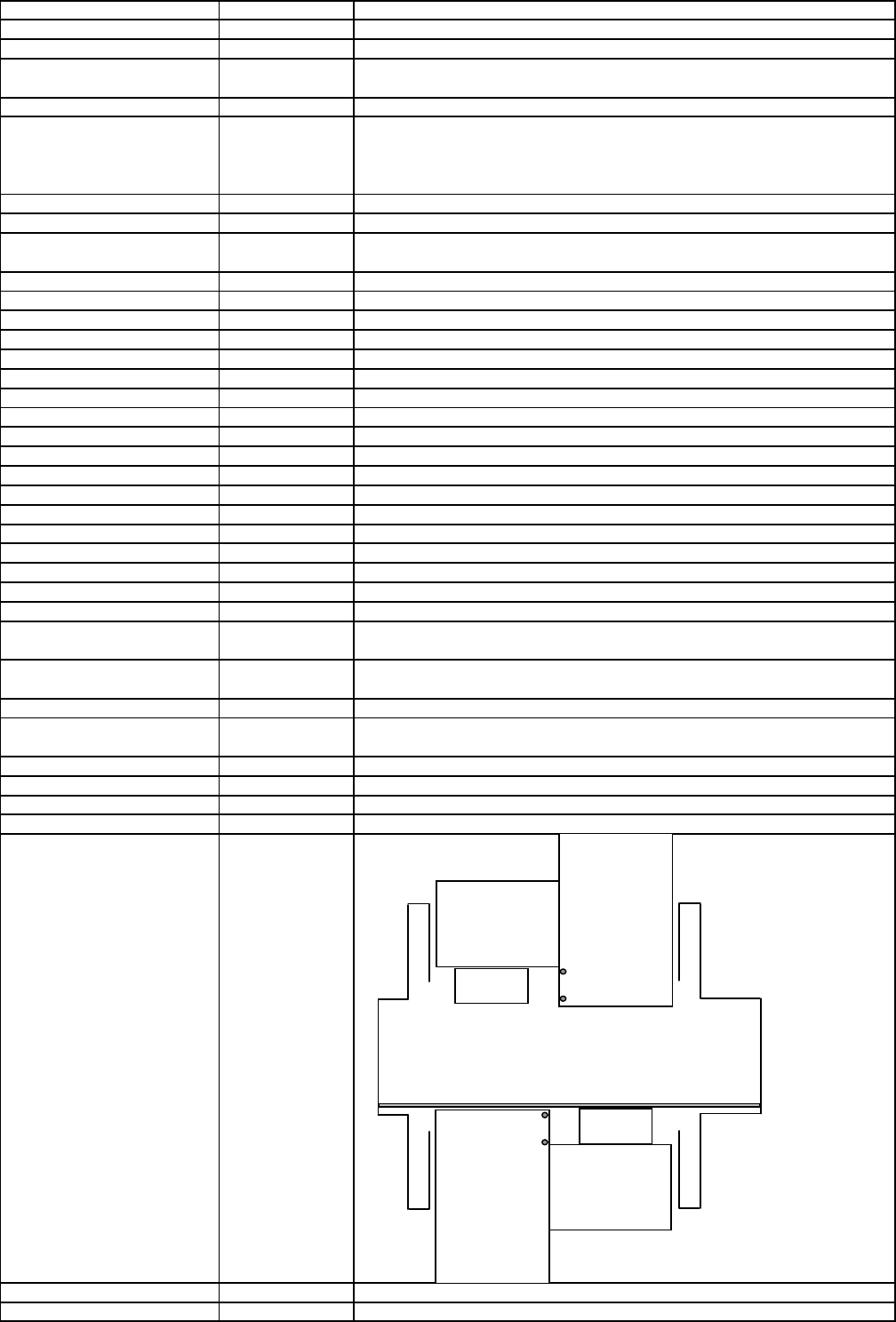
MTC 3
for Portal1
M2
M1
M1
M2
MTC 1
for Portal2
Edition 1.0 3 REAL_MA_e.xls REAL.MA SD EA1 S GC Training

\ MTC2_Marke1_Pos_y_soll
\
0,
normal Feeder area no MTC to moun
t
\ MTC3_Marke1_Pos_x_soll
\
0,
Only for S25HM
X
\ MTC3_Marke1_Pos_y_soll
\
0,
Only for S25HM
X
\ MTC4_Marke1_Pos_x_soll
\
0,
normal Feeder area no MTC to moun
t
\ MTC4_Marke1_Pos_y_soll
\
0,
normal Feeder area no MTC to moun
t
\ MTC1_Marke1_Pos_x_ist
\
0,
Only for S25HM
X
\ MTC1_Marke1_Pos_y_ist
\
0,
Only for S25HM
X
\ MTC2_Marke1_Pos_x_ist
\
0,
normal Feeder area no MTC to moun
t
\ MTC2_Marke1_Pos_y_ist
\
0,
normal Feeder area no MTC to moun
t
\ MTC3_Marke1_Pos_x_ist
\
0,
Only for S25HM
X
\ MTC3_Marke1_Pos_y_ist
\
0,
Only for S25HM
X
\ MTC4_Marke1_Pos_x_ist
\
0,
normal Feeder area no MTC to moun
t
\ MTC4_Marke1_Pos_y_ist
\
0,
normal Feeder area no MTC to moun
t
\ MTC1_Marke2_Pos_x_soll
\
0,
Only for S25HM
X
\ MTC1_Marke2_Pos_y_soll
\
0,
Only for S25HM
X
\ MTC2_Marke2_Pos_x_soll
\
0,
normal Feeder area no MTC to moun
t
\ MTC2_Marke2_Pos_y_soll
\
0,
normal Feeder area no MTC to moun
t
\ MTC3_Marke2_Pos_x_soll
\
0,
Only for S25HM
X
\ MTC3_Marke2_Pos_y_soll
\
0,
Only for S25HM
X
\ MTC4_Marke2_Pos_x_soll
\
0,
normal Feeder area no MTC to moun
t
\ MTC4_Marke2_Pos_y_soll
\
0,
normal Feeder area no MTC to moun
t
\ MTC1_Marke2_Pos_x_ist
\
0,
Only for S25HM
X
\ MTC1_Marke2_Pos_y_ist
\
0,
Only for S25HM
X
\ MTC2_Marke2_Pos_x_ist
\
0,
normal Feeder area no MTC to moun
t
\ MTC2_Marke2_Pos_y_ist
\
0,
normal Feeder area no MTC to moun
t
\ MTC3_Marke2_Pos_x_ist
\
0,
Only for S25HM
X
\ MTC3_Marke2_Pos_y_ist
\
0,
Only for S25HM
X
\ MTC4_Marke2_Pos_x_ist
\
0,
normal Feeder area no MTC to moun
t
\ MTC4_Marke2_Pos_y_ist
\
0|
normal Feeder area no MTC to moun
t
\ Grenzwerte
\
limits
\ Transportbreite_Min_Band1
\
50000,
minimal Transport width Transport1 (Right TSP at fixed TSP side right)
\ Transportbreite_Max_Band1
\
216000,
maximal Transport width Transport1 (Right TSP at fixed TSP side right)
\ Transportbreite_Min_Band2
\
50000,
minimal Transport width Transport1 (left TSP at fixed TSP side right)
\ Transportbreite_Max_Band2
\
216000|
maximal Transport width Transport1 (left TSP at fixed TSP side right)
\ Kopf_Offsets \
Distance RV-comp.-camera center to turning axis of the 2
n
d
placement head of the
gantry (mean only for F machines with 40X SW)
\ Portal 1 \
\ Portal-ID \
1]
Gantry -Ident number.
\ Kopf 1 \ Head 1 RV Head is always the reference on the gantry
\ Kopf_Offset_X \
0,
\ Kopf_Offset_Y \
0]
\ Kopf 2 \
\ Kopf_Offset_X \
0,
Head 2 is not available on this machine type therefor value is 0
\ Kopf_Offset_Y \
0>
\ Portal 2 \
\ Portal-ID \
2]
\ Kopf 1 \
\ Kopf_Offset_X \
0,
\ Kopf_Offset_Y \
0]
\ Kopf 2 \
\ Kopf_Offset_X \
0,
\ Kopf_Offset_Y \
0>
\ Portal 3 \
\ Portal-ID \
3]
\ Kopf 1 \
\ Kopf_Offset_X \
0,
\ Kopf_Offset_Y \
0]
\ Kopf 2 \
\ Kopf_Offset_X \
0,
\ Kopf_Offset_Y \
0>
\ Portal 4 \
\ Portal-ID \
4]
\ Kopf 1 \
\ Kopf_Offset_X \
0,
\ Kopf_Offset_Y \
0]
\ Kopf 2 \
\ Kopf_Offset_X \
0,
\ Kopf_Offset_Y \
0
Edition 1.0 4 REAL_MA_e.xls REAL.MA SD EA1 S GC Training