HS50_advance_level 1_20200522_221201 (1).pdf - 第307页
\ MTC2_Marke1_Pos_y_soll \ 0, normal Feeder area no MTC to moun t \ MTC3_Marke1_Pos_x_soll \ 0, Only for S25HM X \ MTC3_Marke1_Pos_y_soll \ 0, Only for S25HM X \ MTC4_Marke1_Pos_x_soll \ 0, normal Feeder area no MTC to m…
\ SP4_Marke1_Pos_y_soll \
1545750,
Y-coordinate feeder table 4 track 1 Xnominal 4
2
\ SP_Offset_Marke_X \
31600,
this is the X-dimension of one feeder position
\ SP_Offset_Marke_Y \
0,
Y-coordinate of the fiducial define the Y-position of the component table
\ SP1_Korr_AX \
1.000014E+000,
calculation of the real fiducial positions with matrix calculation:
X
12ist = (X11soll+ 11*31600) * AX+Y11soll* BX+VX
\ SP1_Korr_BX \
1.524745E-004,
X
11ist = X11soll * AX+Y11soll* BX+VX
\ SP1_Korr_VX \
-6.189378E+002,
To pick up a comp. the nom.position is taken from feed.setup data file of LC. X-
Feed-ist = Xtrack-soll* AX+Ytrack-soll* BX+VX + Xpickoffset-Feedtype +Xlearn
this calculation is done for each used track in the set up. for the following comp.
tables on each refering comp.table.
\ SP1_Korr_AY \
-1.524745E-004,
Y12ist = (X11soll + 11*31600) * AY+Y11soll* BY+VY
\ SP1_Korr_BY \
1.000014E+000,
Y11ist = X11soll * AY+Y11soll* BY+VY
\ SP1_Korr_VY \
-2.385713E+001,
Y-Feed-ist = Xtrack-soll * AY+Ytrack-soll* BY+VY +Ypickoffset-Feedtype +Ylearn
\ SP2_Korr_AX \
1.000000E+000,
X
22ist = (X21soll +11*31600)* AX+Y21soll* BX+VX
\ SP2_Korr_BX \
0.000000E+000,
X
21ist = X21soll * AX+Y21soll* BX+VX
\ SP2_Korr_VX \
-5.660000E+002,
component pickup coordinate see example calculation on feeder table 1
\ SP2_Korr_AY \
0.000000E+000,
Y22ist = (Y21soll + 11*31600) * AY+Y21soll* BY+VY
\ SP2_Korr_BY \
1.000000E+000,
Y21ist = Y21soll * AY+Y21soll* BY+VY
\ SP2_Korr_VY \
-1.810000E+002,
component pickup coordinate see example calculation on feeder table 1
\ SP3_Korr_AX \
9.999999E-001,
X
32ist = (X31soll -11*31600)* AX+Y31soll* BX+VX
\ SP3_Korr_BX \
-3.452670E-004,
X
31ist = X31soll * AX+Y31soll* BX+VX
\ SP3_Korr_VX \
-1.620737E+001,
component pickup coordinate see example calculation on feeder table 1
\ SP3_Korr_AY \
3.452670E-004,
Y32ist = (Y31soll - 11*31600) * AY+Y31soll* BY+VY
\ SP3_Korr_BY \
9.999999E-001,
Y31ist = Y31soll * AY+Y31soll* BY+VY
\ SP3_Korr_VY \
-5.491860E+002,
component pickup coordinate see example calculation on feeder table 1
\ SP4_Korr_AX \
1.000170E+000,
X
42ist = (X41soll -11*31600)* AX+Y41soll* BX+VX
\ SP4_Korr_BX \
4.315317E-005,
X
41ist = X41soll * AX+Y41soll* BX+VX
\ SP4_Korr_VX \
-7.065124E+002,
component pickup coordinate see example calculation on feeder table 1
\ SP4_Korr_AY \
-4.315317E-005,
Y42ist = (Y41soll - 11*31600) * AY+Y41soll* BY+VY
\ SP4_Korr_BY \
1.000170E+000,
Y41ist = Y41soll * AY+Y41soll* BY+VY
\ SP4_Korr_VY \
-3.418585E+002,
component pickup coordinate see example calculation on feeder table 1
\ Hoehenverm_x_pg1 \
788000,
X
- nozzle length measurement position (height measurment position) for gantry1 and
4. Single- or double transport right side fixed.
\ Hoehenverm_y_pg1 \
713450,
Y-nozzle length measurement position (height measurment position) for gantry1 and
4 at: DT-Rright| DT-Left is around. 1198050
\ Hoehenverm_x_pg2
\
1255000,
X
- nozzle length measurement position for gantry2 and
3
\ Hoehenverm_y_pg2 \
713450,
Y-nozzle length measurement position for gantry 2 and 3 at: DT-Right | DT-Left is
arround 1198050)
\ Kalibrierteilpos_x_pg1
\
720096,
pick up position for calibration tool for for the gantries 1 and 4
\ Kalibrierteilpos_y_pg1 \
713567,
pick up position for calibration tool for for the gantries 1 and 4
\ Kalibrierteilpos_x_pg2
\
1323243,
pick up position for calibration tool for for the gantries 2 and 3
\ Kalibrierteilpos_y_pg2 \
713604,
pick up position for calibration tool for for the gantries 2 and 3
\ MTC1_Marke1_Pos_x_soll \
0,
Only for S25HMX
(MTC for HS 50 not prepared yet)
\ MTC1_Marke1_Pos_y_soll
\
0,
Only for S25HM
X
\ MTC2_Marke1_Pos_x_soll
\
0,
normal Feeder area no MTC to moun
t
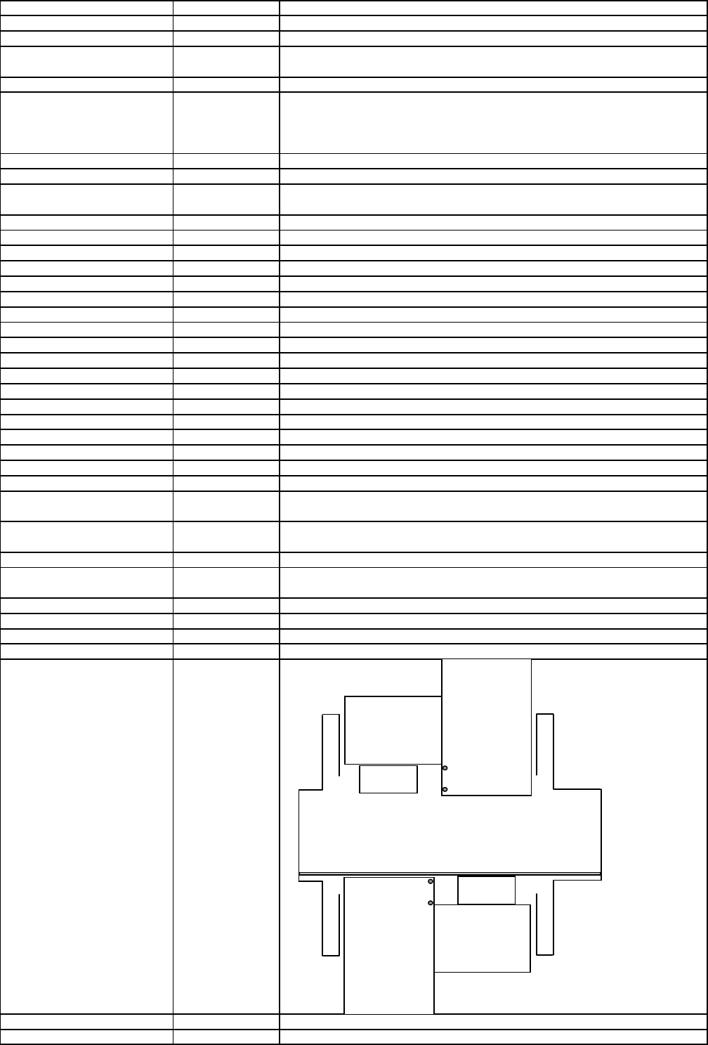
MTC 3
for Portal1
M2
M1
M1
M2
MTC 1
for Portal2
Edition 1.0 3 REAL_MA_e.xls REAL.MA SD EA1 S GC Training

\ MTC2_Marke1_Pos_y_soll
\
0,
normal Feeder area no MTC to moun
t
\ MTC3_Marke1_Pos_x_soll
\
0,
Only for S25HM
X
\ MTC3_Marke1_Pos_y_soll
\
0,
Only for S25HM
X
\ MTC4_Marke1_Pos_x_soll
\
0,
normal Feeder area no MTC to moun
t
\ MTC4_Marke1_Pos_y_soll
\
0,
normal Feeder area no MTC to moun
t
\ MTC1_Marke1_Pos_x_ist
\
0,
Only for S25HM
X
\ MTC1_Marke1_Pos_y_ist
\
0,
Only for S25HM
X
\ MTC2_Marke1_Pos_x_ist
\
0,
normal Feeder area no MTC to moun
t
\ MTC2_Marke1_Pos_y_ist
\
0,
normal Feeder area no MTC to moun
t
\ MTC3_Marke1_Pos_x_ist
\
0,
Only for S25HM
X
\ MTC3_Marke1_Pos_y_ist
\
0,
Only for S25HM
X
\ MTC4_Marke1_Pos_x_ist
\
0,
normal Feeder area no MTC to moun
t
\ MTC4_Marke1_Pos_y_ist
\
0,
normal Feeder area no MTC to moun
t
\ MTC1_Marke2_Pos_x_soll
\
0,
Only for S25HM
X
\ MTC1_Marke2_Pos_y_soll
\
0,
Only for S25HM
X
\ MTC2_Marke2_Pos_x_soll
\
0,
normal Feeder area no MTC to moun
t
\ MTC2_Marke2_Pos_y_soll
\
0,
normal Feeder area no MTC to moun
t
\ MTC3_Marke2_Pos_x_soll
\
0,
Only for S25HM
X
\ MTC3_Marke2_Pos_y_soll
\
0,
Only for S25HM
X
\ MTC4_Marke2_Pos_x_soll
\
0,
normal Feeder area no MTC to moun
t
\ MTC4_Marke2_Pos_y_soll
\
0,
normal Feeder area no MTC to moun
t
\ MTC1_Marke2_Pos_x_ist
\
0,
Only for S25HM
X
\ MTC1_Marke2_Pos_y_ist
\
0,
Only for S25HM
X
\ MTC2_Marke2_Pos_x_ist
\
0,
normal Feeder area no MTC to moun
t
\ MTC2_Marke2_Pos_y_ist
\
0,
normal Feeder area no MTC to moun
t
\ MTC3_Marke2_Pos_x_ist
\
0,
Only for S25HM
X
\ MTC3_Marke2_Pos_y_ist
\
0,
Only for S25HM
X
\ MTC4_Marke2_Pos_x_ist
\
0,
normal Feeder area no MTC to moun
t
\ MTC4_Marke2_Pos_y_ist
\
0|
normal Feeder area no MTC to moun
t
\ Grenzwerte
\
limits
\ Transportbreite_Min_Band1
\
50000,
minimal Transport width Transport1 (Right TSP at fixed TSP side right)
\ Transportbreite_Max_Band1
\
216000,
maximal Transport width Transport1 (Right TSP at fixed TSP side right)
\ Transportbreite_Min_Band2
\
50000,
minimal Transport width Transport1 (left TSP at fixed TSP side right)
\ Transportbreite_Max_Band2
\
216000|
maximal Transport width Transport1 (left TSP at fixed TSP side right)
\ Kopf_Offsets \
Distance RV-comp.-camera center to turning axis of the 2
n
d
placement head of the
gantry (mean only for F machines with 40X SW)
\ Portal 1 \
\ Portal-ID \
1]
Gantry -Ident number.
\ Kopf 1 \ Head 1 RV Head is always the reference on the gantry
\ Kopf_Offset_X \
0,
\ Kopf_Offset_Y \
0]
\ Kopf 2 \
\ Kopf_Offset_X \
0,
Head 2 is not available on this machine type therefor value is 0
\ Kopf_Offset_Y \
0>
\ Portal 2 \
\ Portal-ID \
2]
\ Kopf 1 \
\ Kopf_Offset_X \
0,
\ Kopf_Offset_Y \
0]
\ Kopf 2 \
\ Kopf_Offset_X \
0,
\ Kopf_Offset_Y \
0>
\ Portal 3 \
\ Portal-ID \
3]
\ Kopf 1 \
\ Kopf_Offset_X \
0,
\ Kopf_Offset_Y \
0]
\ Kopf 2 \
\ Kopf_Offset_X \
0,
\ Kopf_Offset_Y \
0>
\ Portal 4 \
\ Portal-ID \
4]
\ Kopf 1 \
\ Kopf_Offset_X \
0,
\ Kopf_Offset_Y \
0]
\ Kopf 2 \
\ Kopf_Offset_X \
0,
\ Kopf_Offset_Y \
0
Edition 1.0 4 REAL_MA_e.xls REAL.MA SD EA1 S GC Training

} end of file
Edition 1.0 5 REAL_MA_e.xls REAL.MA SD EA1 S GC Training