HS50_advance_level 1_20200522_221201 (1).pdf - 第326页
Studen t Guide HS-50 A dvanced I 06/200 2 Edition 8 Gantry 3 8.2 Proximity Sw itch X- / Y - Axis NOTE The distance between bot h proximity swi tches of the x - and y- axis, is set to 0.2 mm. (Measured from the op eration…

06/2002 Edition Student Guide HS-50 Advanced I
8 Gantry
2
8.1.4 Fitting the PCB Camera Module
➠ Place the Camera Module into the machine and fix the cameara with the 3 Allen screws
(see Fig: Fig. 8.1 - 1).
➠ Fit the cables properly into the machine and fix the cables with with straps.
➠ Connect the Cable Camera Signal (see Fig: fig 8.3 - 1 Pos: 2) and cable illumination control
(see Fig: fig 8.3 - 1 Pos: 3) to the Head board HS-50.
8.1.5 Settings
➠ Start the placement system.
➠ Use the SITEST program to calibrate the PCB camera.
Student Guide HS-50 Advanced I 06/2002 Edition
8 Gantry
3
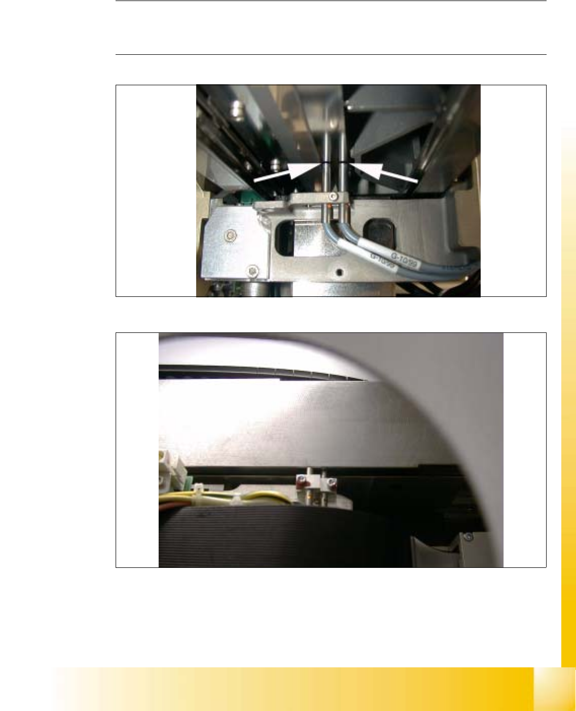
8.2 Proximity Switch X- / Y- Axis
NOTE
The distance between both proximity switches of the x- and y- axis, is set to 0.2 mm.
(Measured from the operational plane). 8
8
fig 8.2 - 1 Proximity switch, travel range x-axis
8
fig 8.2 - 2 Proximity switch, travel range y-axis, foto made without cover
06/2002 Edition Student Guide HS-50 Advanced I
8 Gantry
4
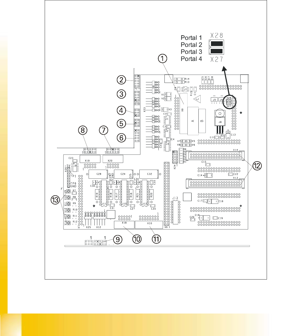
8.3 Settings and Illustrations
8.3.1 Jumper Settings on Head Board S50
8
fig 8.3 - 1 Head board S50