HS50_advance_level 1_20200522_221201 (1).pdf - 第327页
06/2002 E dition Studen t Guide H S-50 Advance d I 8 Gant ry 4 8.3 Settings a nd Illustrati ons 8. 3.1 Jum per Se tti ngs on H ead B oard S50 8 fig 8. 3 - 1 Hea d bo ard S 50
Student Guide HS-50 Advanced I 06/2002 Edition
8 Gantry
3
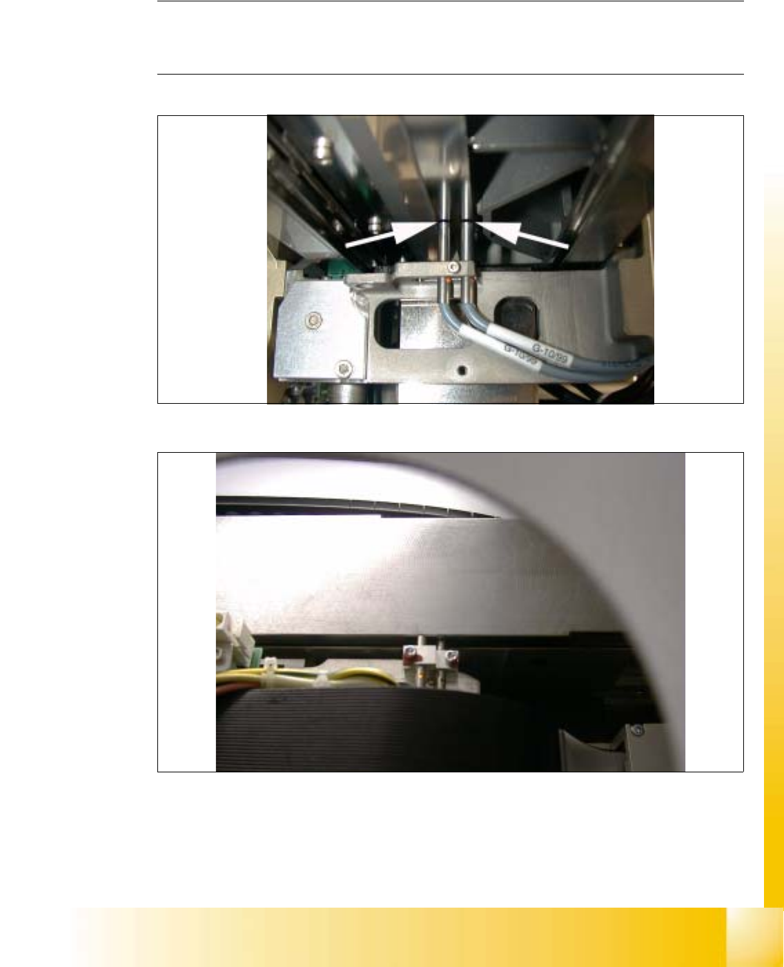
8.2 Proximity Switch X- / Y- Axis
NOTE
The distance between both proximity switches of the x- and y- axis, is set to 0.2 mm.
(Measured from the operational plane). 8
8
fig 8.2 - 1 Proximity switch, travel range x-axis
8
fig 8.2 - 2 Proximity switch, travel range y-axis, foto made without cover
06/2002 Edition Student Guide HS-50 Advanced I
8 Gantry
4
8.3 Settings and Illustrations
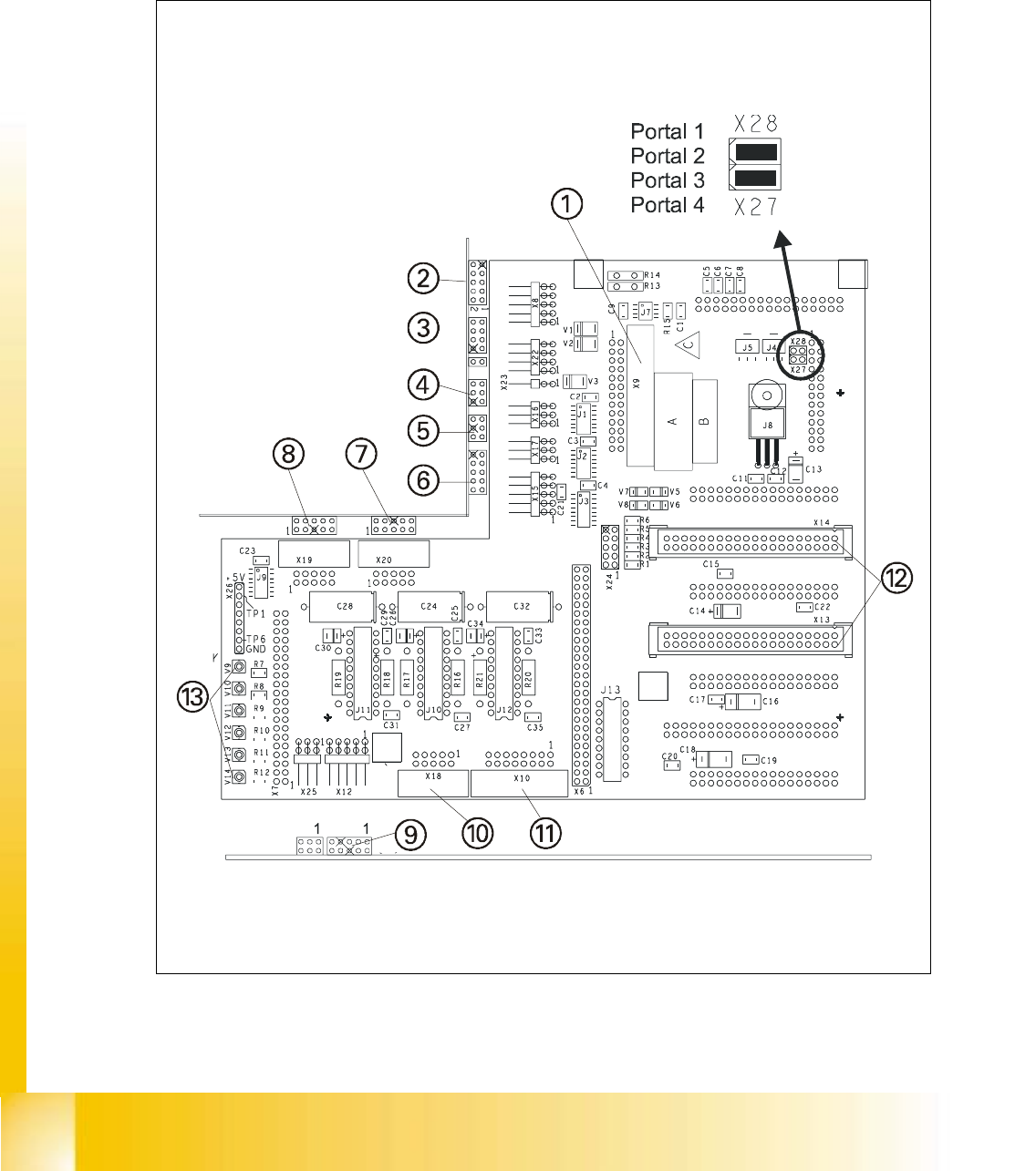
8.3.1 Jumper Settings on Head Board S50
8
fig 8.3 - 1 Head board S50

Student Guide HS-50 Advanced I 06/2002 Edition
8 Gantry
5
KEY:
(1) Component camera
(2) Video signals PCB camera
(3) Illumination PCB camera
(4) Limit switch x-axis
(5) Limit switch x-axis
(6) Track signals x-axis
(7) Ejection of valve drive
(8) Placement of valve drive
(9) Motor / tacho dp - station
(10) Swivel - in motor, dp - station
(11) Vacuum test board
(12) Intermediate distributor SP 6 - 12, digital
(13) LED:
V9 LZOS Light barrier Z-axis upper stop
V10 LZUS Light barrier Z-axis down position
V11 LSOI Light barrier Pick &Place Head top position (not used)
V12 LSZD Light barrier Swivel in and turning dp-station
V13 LSVZ Light barrier Vacuum / air blow Z-axis
V14 LSVA Light barrier Vacuum / air blow reject position