HS50_advance_level 1_20200522_221201 (1).pdf - 第332页
Studen t Guide HS-50 A dvanced I 06/200 2 Edition 8 Gantry 9 8 Fig. 8.3 - 5 S wi tch p oint s Key (1) Switch point end position, gantry 4 / 2 (2) Switch point reference, gantry 4 / 2 (3) Switch point reference, gantry 1 …
06/2002 Edition Student Guide HS-50 Advanced I
8 Gantry
8
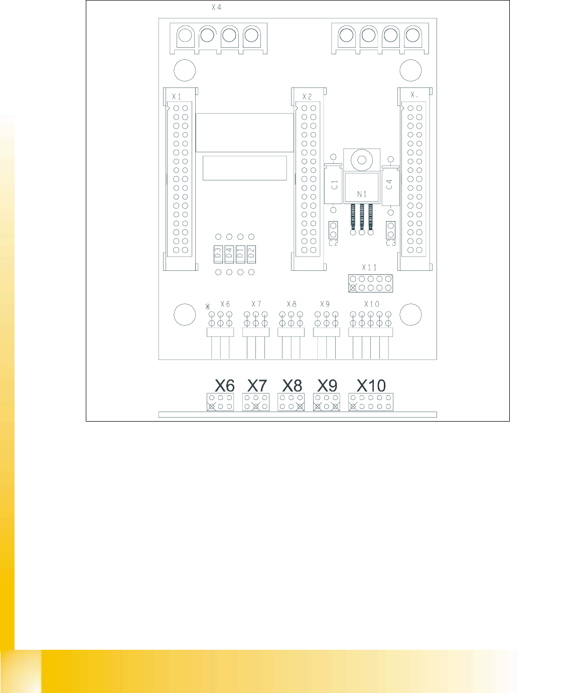
8.3.4 Proximity Switch Connectors on the X- / Y Distributor S50
8
fig 8.3 - 4 X- / Y- distributor S50
KEY:
X6 = Not used 8
X7, X8 = Proximity switch y-axis 8
X9 = Distance sensor 8
X10 = Track signals y-axis 8
8
8
8
8
Student Guide HS-50 Advanced I 06/2002 Edition
8 Gantry
9
8
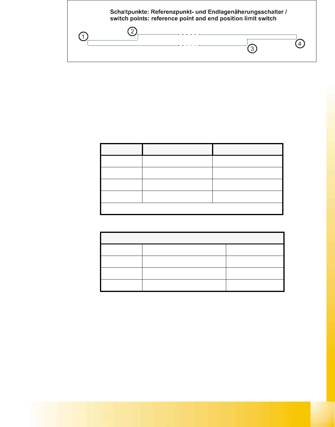
Fig. 8.3 - 5 Switch points
Key
(1) Switch point end position, gantry 4 / 2
(2) Switch point reference, gantry 4 / 2
(3) Switch point reference, gantry 1 /3
(4) Switch point end position, gantry 1 / 3
Proximity switch X7 Proximity switch X8
gantry 1 top bottom
gantry 2 bottom top
gantry 3 top bottom
gantry 4 bottom top
distance sensor X9 only with gantry 1 and 3
Switch points: Reference / end position
1 switch point: end position gantry 2 , 4
2 switch point: reference gantry 2, 4
3 switch point: reference gantry 1, 3
4 switch point: end position gantry 1, 3
06/2002 Edition Student Guide HS-50 Advanced I
8 Gantry
10
8.4 Calibration of the Anti - Crash Board
8.4.1 Test Equipment
– Digital multimeter
– SITEST software
– Anti - crash board for HS-50
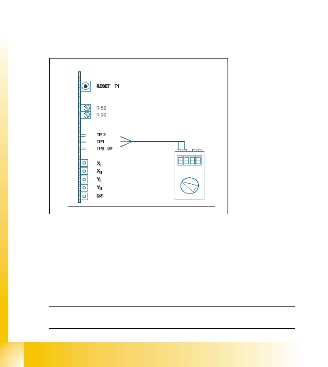
8.4.2 Test Setup
8
fig 8.4 - 1 Test setup for the anti - crash board
KEY:
TP2 = Signal
R82, R92 = Potentiometer 8
TP1 = Signal 8
X
I
, Y
I
= "Error" message for the axes of the left gantry in each work area. 8
X
II
, Y
II
= "Error" message for the axes of the right gantry in each work area.
(Viewpoint from input conveyor).
DIS = Message: Distance sensor activated. 8
NOTE
Adjustments are identical for both gantry groups. 8