HS50_advance_level 1_20200522_221201 (1).pdf - 第334页
Studen t Guide HS-50 A dvanced I 06/200 2 Edition 8 Gantry 11 CAUTION Perform these adjustments only after you pressed the EMERGE NCY STOP button! 8 8.4. 3 Adjustm ent of Dist ance S en s o r Se n sit ivity ➠ Connec t th…
06/2002 Edition Student Guide HS-50 Advanced I
8 Gantry
10
8.4 Calibration of the Anti - Crash Board
8.4.1 Test Equipment
– Digital multimeter
– SITEST software
– Anti - crash board for HS-50
8.4.2 Test Setup
8
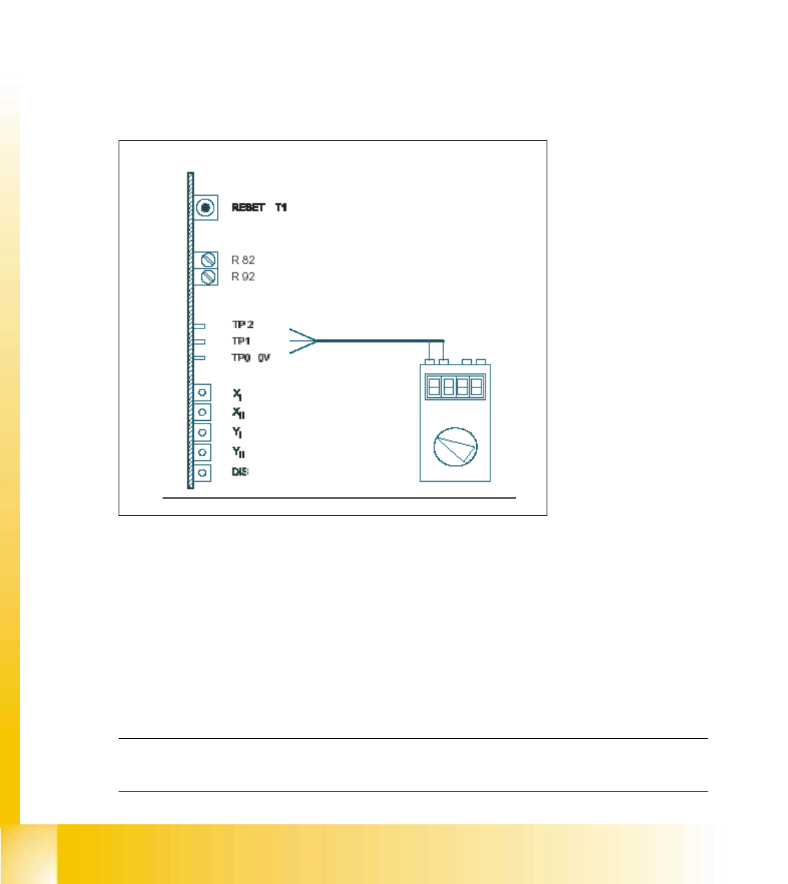
fig 8.4 - 1 Test setup for the anti - crash board
KEY:
TP2 = Signal
R82, R92 = Potentiometer 8
TP1 = Signal 8
X
I
, Y
I
= "Error" message for the axes of the left gantry in each work area. 8
X
II
, Y
II
= "Error" message for the axes of the right gantry in each work area.
(Viewpoint from input conveyor).
DIS = Message: Distance sensor activated. 8
NOTE
Adjustments are identical for both gantry groups. 8

Student Guide HS-50 Advanced I 06/2002 Edition
8 Gantry
11
CAUTION
Perform these adjustments only after you pressed the EMERGENCY STOP button! 8
8.4.3 Adjustment of Distance Sensor Sensitivity
➠ Connect the digital multimeter of the anti - crash board to pin TP 0 (0V) and pin TP 1 (signal).
➠ Move both gantries together.
➠ Use the adjusting screw to set the voltage at the distance sensor to 6V - +/- 0,1 V.
➠ Move the two gantries together until a distance of 100 mm is reached.
(Elastomer spring up to opposite plane).
– The voltage must reach a value of approx. 2V.
8.4.4 Calibration of the Anti - Crash Board
➠
Connect the digital multimeter to the anti - crash board at pin TP2 (signal) and pin TP0 (0V).
➠ Move both gantries together.
➠ Use the potentiometer R82 to adjust the voltage to 0V- +/- 0.05 V.
➠ Move the two gantries together until a distance of 100 mm is reached.
➠ Use the potentiometer R92 to adjust the voltage to 10V- +/- 0.05 V.
➠ Check the 0V- setting one more time.
➠ Repeat the calibration if the reached value is incorrect.
8.4.5 Function Control of the Distance Sensor
8.4.5.1 Preparation
➠ Perform a reference run.
8.4.5.2 Testing Placement Areas I and II
➠ In placement area I, attach a piece of paper in the middle of the machine, at the height of the
distance sensor.
SITEST: 8
➠ Select "Gantry" ==> "Select gantry" ==>
"Axis functions" ==> "Select y-axis" ==> "Position the axis" ==> "Edit values and
accept for target position = 1 300,000 dgts".
06/2002 Edition Student Guide HS-50 Advanced I
8 Gantry
12
➠ Press the START button.
– The axis will stop at the obstacle. The distance sensor has triggered.
➠ Press the EMERGENCY STOP button and remove the obstacle.
➠ Press RESET on the anti - crash board.
➠ Release the EMERGENCY STOP button and press the START button.
➠ Perform a gantry reference run.
➠ Perform the same test with placement area II.
NOTE
For placement area I, select "gantry 3". Edit and accept a target position of 600,000 dgts. 8
8.4.6 Functions Control of the Anti - Crash Board
NOTE
This test is identical for all gantry groups.
DANGER
You must press the EMERGENCY STOP button BEFORE you activate RESET on the anti - crash
board.
If you do not press the EMERGENCY STOP button, the axis will continue traversing immediately
after RESET. 8