HS50_advance_level 1_20200522_221201 (1).pdf - 第35页
Studen t Guide HS-50 A dvanced I 06/200 2 Edition 2 Overview 5 2O v e r v i e w 2. 1 Ele ct r ica l D raw er Fig. 2.1 - 1 Key (1) Power sup ply unit (Pos . 1) (2) Main distribution unit (Pos. 2) (3) Control unit (Pos. 3)…

1 - 4
06/2002 Edition Student Guide HS-50 Advanced I
Contents
4
2.11 Component Changeover Table. . . . . . . . . . . . . . . . . . . . . . . . . . . . . . . . . . . . . . . . . . . . . . . . . . . 28
2.12 Gantry . . . . . . . . . . . . . . . . . . . . . . . . . . . . . . . . . . . . . . . . . . . . . . . . . . . . . . . . . . . . . . . . . . . . . . . 29
2.12.1 Gantries and placement areas. . . . . . . . . . . . . . . . . . . . . . . . . . . . . . . . . . . . . . . . . 29
2.12.2 Coordinate System . . . . . . . . . . . . . . . . . . . . . . . . . . . . . . . . . . . . . . . . . . . . . . . . . 30
2.12.3 The HS-50 is a four gantry machine with AC drives . . . . . . . . . . . . . . . . . . . . . . . . 30
2.12.4 PCB Camera . . . . . . . . . . . . . . . . . . . . . . . . . . . . . . . . . . . . . . . . . . . . . . . . . . . . . . 31
2.13 DLM1 C&P Head Overview. . . . . . . . . . . . . . . . . . . . . . . . . . . . . . . . . . . . . . . . . . . . . . . . . . . . . . 32
2.13.1 Steps when picking up and placing components. . . . . . . . . . . . . . . . . . . . . . . . . . . 33
2.13.2 Overview of the functions of star stations 1 - 12 . . . . . . . . . . . . . . . . . . . . . . . . . . . 34
2.14 Nozzle Changer . . . . . . . . . . . . . . . . . . . . . . . . . . . . . . . . . . . . . . . . . . . . . . . . . . . . . . . . . . . . . . . 35
2.14.1 Nozzle Changer magazine . . . . . . . . . . . . . . . . . . . . . . . . . . . . . . . . . . . . . . . . . . . 35
2.15 Control structure . . . . . . . . . . . . . . . . . . . . . . . . . . . . . . . . . . . . . . . . . . . . . . . . . . . . . . . . . . . . . . 36
2.15.1 Line Computer or Siplace Pro computer . . . . . . . . . . . . . . . . . . . . . . . . . . . . . . . . . 36
2.15.2 Station Computer. . . . . . . . . . . . . . . . . . . . . . . . . . . . . . . . . . . . . . . . . . . . . . . . . . . 37
2.15.3 Machine Controller. . . . . . . . . . . . . . . . . . . . . . . . . . . . . . . . . . . . . . . . . . . . . . . . . . 37
2.16 Software . . . . . . . . . . . . . . . . . . . . . . . . . . . . . . . . . . . . . . . . . . . . . . . . . . . . . . . . . . . . . . . . . . . . . 38
Student Guide HS-50 Advanced I 06/2002 Edition
2 Overview
5
2Overview
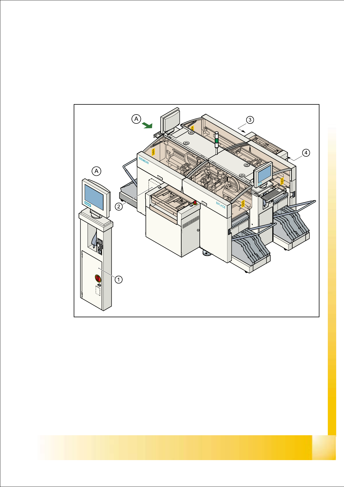
2.1 Electrical Drawer
Fig. 2.1 - 1
Key
(1) Power supply unit (Pos. 1)
(2) Main distribution unit (Pos. 2)
(3) Control unit (Pos. 3)
(4) Servo unit (Pos. 4)
06/2002 Edition Student Guide HS-50 Advanced I
2 Overview
6
Nominal Voltage 2
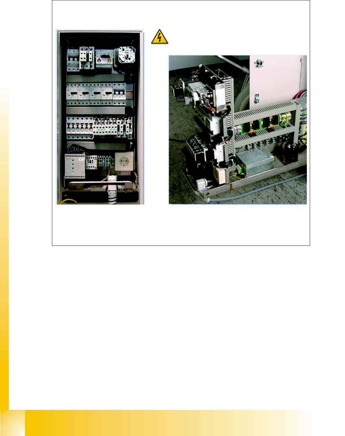
The Power Supply unit produces
the most of the supply voltages
required to operate the machine
The Power Supply unit can be removed from the
housing for service purposes
Parts of the machine conduct highly danger-
ous voltages, even when the main switch is off.
Please observe the safety guidelines