HS50_advance_level 1_20200522_221201 (1).pdf - 第351页
06/2002 E dition Studen t Guide H S-50 Advance d I 9 Co nveyor Syst em 10 9.2. 1 Adjustmen t of Supers onic S ensitivit y ➠ Set conveyor width to minimu m widt h. NOTE Adjusting the proximi ty s w it ches "input /ou…
Student Guide HS-50 Advanced I 06/2002 Edition
9 Conveyor System
9
9.2 Sonar Proximity Switches and Proximity Modules
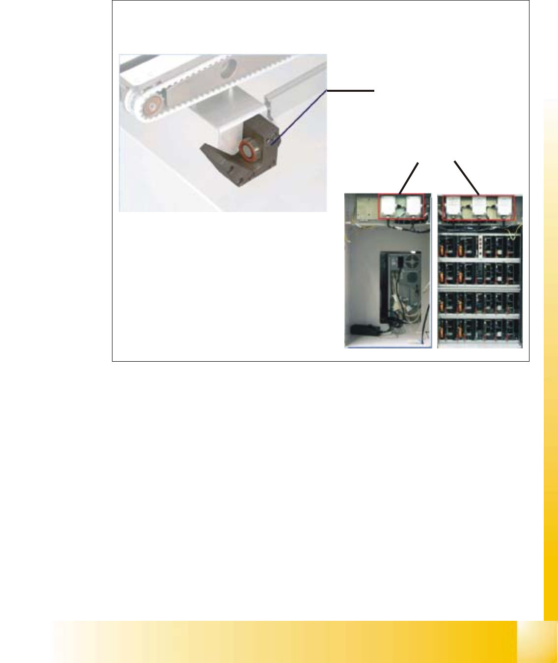
Fig. 9.2 - 1 Sonar Proximity switches and modules
– Sonar proximity switches are used to control the PCB conveyor. These sensors operate
contact-free (by means of sound waves) and monitor the position of the PCB.
– Their level of sensitivity is set on the proximity switch modules lacated at the rear of the station
computer above the servo unit.
Proximity switch modules
Sonar proximity switch
Conveyor control unit

06/2002 Edition Student Guide HS-50 Advanced I
9 Conveyor System
10
9.2.1 Adjustment of Supersonic Sensitivity
➠ Set conveyor width to minimum width.
NOTE
Adjusting the proximity switches "input /output conveyor belt", make sure that the proximity
switches do not switch to the movable bearers of the conveyor belt. 9
– The amplifiers for the adjustment of the ultrasonic sensors are located behind the door of the
right side of the input conveyor belt and behind the door above the servo unit of the output
conveyor belt.
– The HS-50 has five conveyor areas:
- Input
- Placement 1
- Intermediate
- Placement 2
- Output
9.2.2 Input Conveyor
➠ Slide the PCB over the proximity switch "Input conveyor".
➠ Turn the adjusting screw on the amplifier of the proximity switch "Input conveyor" fully counter-
clockwise.
– The yellow LED of the amplifier begins to flash.
➠ Slowly, turn the adjusting screw of the proximity switch amplifier to the right, until the LED light
remains illuminated.
➠ Hold the PCB approximately 5 mm above the PCB conveyor.
– The LED must go out.
➠ Adjust again, if the switching point of the proximity switch remains outside the
selected range.
9.2.3 Placement 1 and 2 Conveyor
➠ Slide the PCB over the proximity switch "Placement 1 or 2 conveyor".
➠ Make shure that the clamping is not activated.
➠ Move the PCB to the proximity switch "Center conveyor".
➠ Turn the adjusting screw of the proximity switch amplifier "Center conveyor" fully counterclock-
wise.
– The yellow LED of the amplifier begins to flash.

Student Guide HS-50 Advanced I 06/2002 Edition
9 Conveyor System
11
➠ Slowly, turn the adjusting screw of the proximity switch amplifier to the right, until the LED light
remains illuminated.
➠ Hold the PCB approximately 5 mm above the PCB conveyor.
– The LED must go out.
➠ If the switching point of the proximity switch amplifier is outside the selected range, correct it
accordingly.
Note:
All adjustments are the same except the location in the machine
9.2.4 Output Conveyor
➠
Slide the PCB over the proximity switch "Output conveyor".
➠ Turn the adjusting screw of the proximity switch amplifier "Output conveyor" fully counterclock-
wise.
– The yellow LED of the amplifier begins to flash.
➠ Slowly, turn the adjusting screw of the proximity switch amplifier to the right, until the LED light
remains illuminated.
➠ Hold the PCB approximately 5 mm above the PCB conveyor.
– The LED must go out.
➠ If the switching point of the proximity switch amplifier is outside the selected range, correct it
accordingly.
➠ Use the instructions for the adjustment of the first conveyor to adjust the second conveyor ac-
cordingly.