HS50_advance_level 1_20200522_221201 (1).pdf - 第352页
Studen t Guide HS-50 A dvanced I 06/200 2 Edition 9 Con veyor System 11 ➠ Slo wly , turn the adjust ing screw of the proxim it y switch am plifier to the right, until the LED light remain s i lluminated. ➠ Hold the PCB a…

06/2002 Edition Student Guide HS-50 Advanced I
9 Conveyor System
10
9.2.1 Adjustment of Supersonic Sensitivity
➠ Set conveyor width to minimum width.
NOTE
Adjusting the proximity switches "input /output conveyor belt", make sure that the proximity
switches do not switch to the movable bearers of the conveyor belt. 9
– The amplifiers for the adjustment of the ultrasonic sensors are located behind the door of the
right side of the input conveyor belt and behind the door above the servo unit of the output
conveyor belt.
– The HS-50 has five conveyor areas:
- Input
- Placement 1
- Intermediate
- Placement 2
- Output
9.2.2 Input Conveyor
➠ Slide the PCB over the proximity switch "Input conveyor".
➠ Turn the adjusting screw on the amplifier of the proximity switch "Input conveyor" fully counter-
clockwise.
– The yellow LED of the amplifier begins to flash.
➠ Slowly, turn the adjusting screw of the proximity switch amplifier to the right, until the LED light
remains illuminated.
➠ Hold the PCB approximately 5 mm above the PCB conveyor.
– The LED must go out.
➠ Adjust again, if the switching point of the proximity switch remains outside the
selected range.
9.2.3 Placement 1 and 2 Conveyor
➠ Slide the PCB over the proximity switch "Placement 1 or 2 conveyor".
➠ Make shure that the clamping is not activated.
➠ Move the PCB to the proximity switch "Center conveyor".
➠ Turn the adjusting screw of the proximity switch amplifier "Center conveyor" fully counterclock-
wise.
– The yellow LED of the amplifier begins to flash.

Student Guide HS-50 Advanced I 06/2002 Edition
9 Conveyor System
11
➠ Slowly, turn the adjusting screw of the proximity switch amplifier to the right, until the LED light
remains illuminated.
➠ Hold the PCB approximately 5 mm above the PCB conveyor.
– The LED must go out.
➠ If the switching point of the proximity switch amplifier is outside the selected range, correct it
accordingly.
Note:
All adjustments are the same except the location in the machine
9.2.4 Output Conveyor
➠
Slide the PCB over the proximity switch "Output conveyor".
➠ Turn the adjusting screw of the proximity switch amplifier "Output conveyor" fully counterclock-
wise.
– The yellow LED of the amplifier begins to flash.
➠ Slowly, turn the adjusting screw of the proximity switch amplifier to the right, until the LED light
remains illuminated.
➠ Hold the PCB approximately 5 mm above the PCB conveyor.
– The LED must go out.
➠ If the switching point of the proximity switch amplifier is outside the selected range, correct it
accordingly.
➠ Use the instructions for the adjustment of the first conveyor to adjust the second conveyor ac-
cordingly.
06/2002 Edition Student Guide HS-50 Advanced I
9 Conveyor System
12
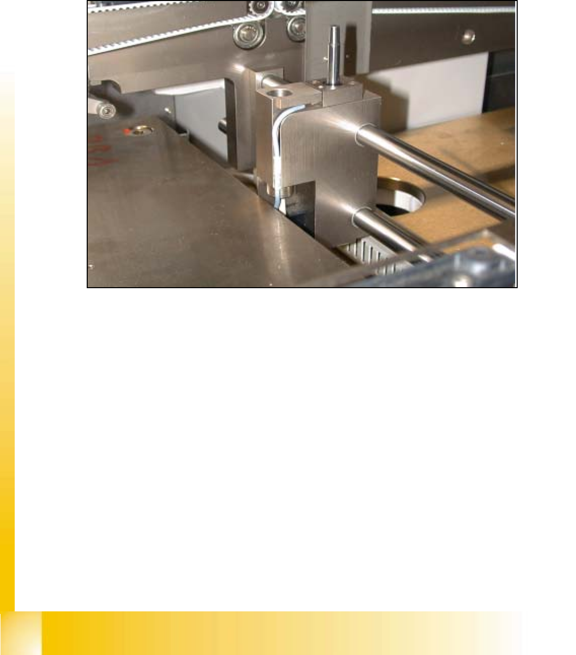
9.3 Adjustment of the Proximity Switches PCB Stop-
per
9
fig 9.3 - 1 Proximity switch stopper
➠ Utilize the menu for the extraction of the PCB stopper.
SITEST: 9
➠ Select "Transport functions" ==> "PCB conveyor 1 or 2" ==> "Stopper 1 (2)
retract / extract".
➠ Carefully, move the proximity switch until contact is reached.
➠ Pull back the proximity switch until a small gap of approximately 0.2 mm is reached, while the
contact must not get interrupted.