HS50_advance_level 1_20200522_221201 (1).pdf - 第356页
Studen t Guide HS-50 A dvanced I 06/200 2 Edition 9 Con veyor System 15 9 .5 Li f t i ng tabl e an d mot o r 9.5. 1 Function ality of th e clampi ng syst em Fig. 9.5 - 1 Cla mping syste m The PCBs lie on convey or be lts…
06/2002 Edition Student Guide HS-50 Advanced I
9 Conveyor System
14
9
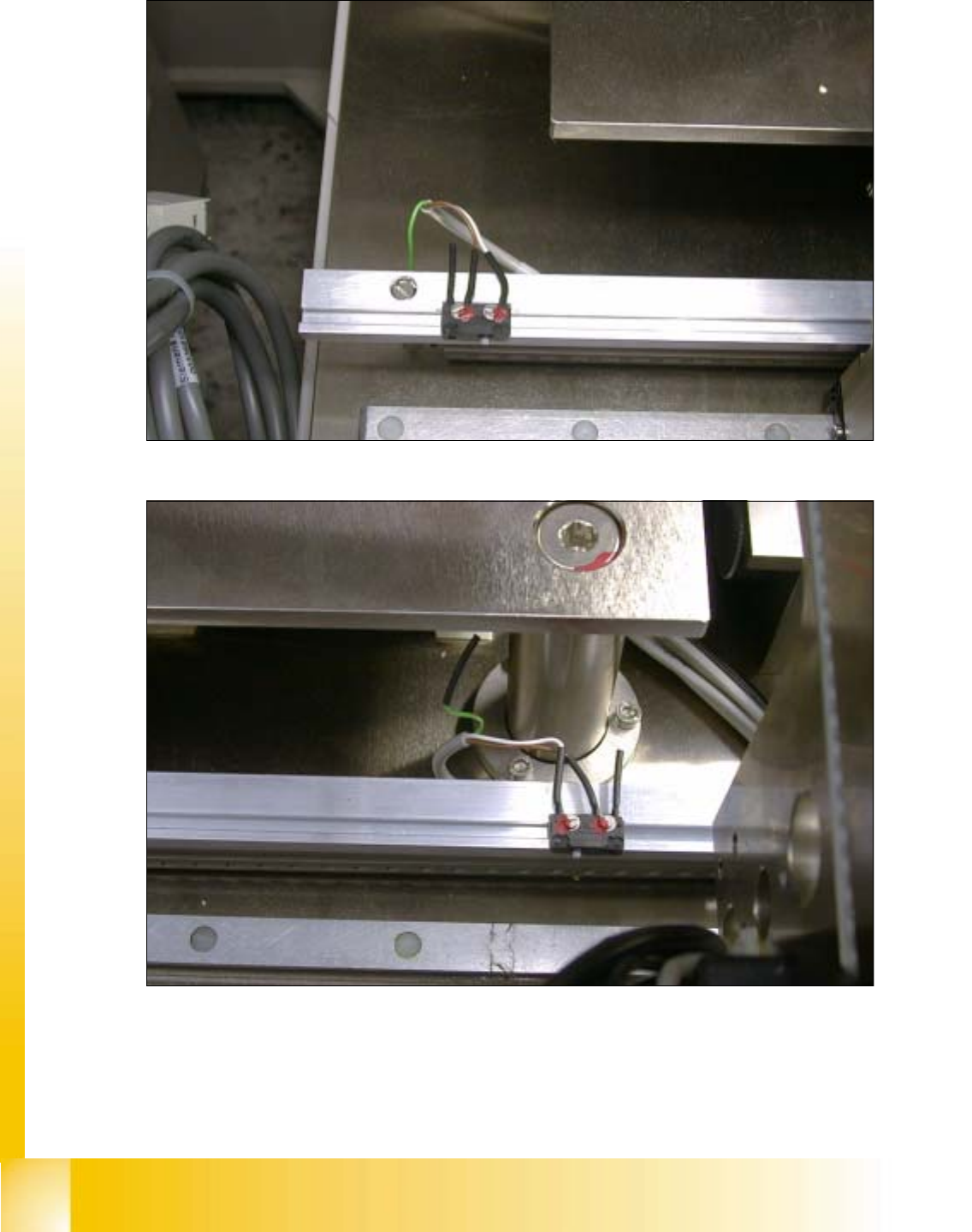
fig 9.4 - 2 Limit switch conveyor width adjustment, maximum widht
9
fig 9.4 - 3 Limit switch conveyor width adjustment, minimum widht
Student Guide HS-50 Advanced I 06/2002 Edition
9 Conveyor System
15
9.5 Lifting table and motor
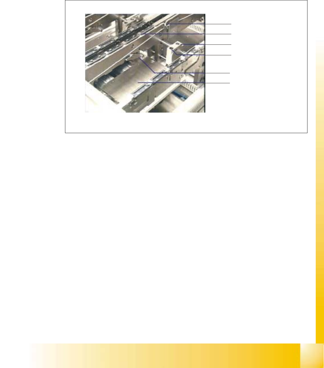
9.5.1 Functionality of the clamping system
Fig. 9.5 - 1 Clamping system
The PCBs lie on conveyor belts, which are driven by DC motors. The transport process is moni-
tored by means of ultrasonic sensors (proximity switches).
A lifting table is raised by cams and the left- and right-hand clamping combs are applied by means
of a rocking lever.
Conveyor belt
PCB clamp
Stopper
Proximity switc
h
Rocking lever
Lifting table

06/2002 Edition Student Guide HS-50 Advanced I
9 Conveyor System
16
9.5.2 Lifting table
DANGER
Comply with the safety instructions. 9
CAUTION
The customer must not loosen screws secured with loctite (e.g., on the screws fastening the guide
pillars of the lifting table). 9
NOTE
The lifting table plate must be removed, for example, in order to exchange hold-down device and
compression spring or to work in the area under the lifting table plate. For the layout of the lifting
table and the lifting table motors 9
➠ Removing the Lifting Table
➠ Move the conveyor to maximum width.
➠ Move the Y-gantries into the area outside the PCB conveyor.
➠ Turn off the machine at the main switch and disconnect the machine from the mains.
➠ Conscientiously secure the machine against reactivation during servicing work.
➠ In the pertinent conveyor area, on the fixed and the movable conveyor side, slightly loosen the
M3 set screw on the ball bearing of each rocking lever.
➠ Being careful not to lose the set screw, remove the two ball bearings.
WARNING
During the subsequent lifting of the lifting table plate there is a risk of body members being
pinched, crushed or cut off, e.g., between the outer edges of the lifting table plate and the con-
veyor assemblies. 9
➠ Holding the lifting table plate with both hands, lift it up vertically.
➠ Make certain the lifting table is not tilted while being lifted, otherwise the guide pillars could be
bent in the process.
CAUTION
Do not place the lifting table plate on its side and do not support it on the guide pillars. 9
➠ Place the lifting table plate upside down on a clean, flat surface.