HS50_advance_level 1_20200522_221201 (1).pdf - 第358页
Studen t Guide HS-50 A dvanced I 06/200 2 Edition 9 Con veyor System 17 ➠ Carry out the steps in the area under th e lif t ing table plate (e.g. , exchange t he proximity swit ch for the m otor or the lifting table or th…

06/2002 Edition Student Guide HS-50 Advanced I
9 Conveyor System
16
9.5.2 Lifting table
DANGER
Comply with the safety instructions. 9
CAUTION
The customer must not loosen screws secured with loctite (e.g., on the screws fastening the guide
pillars of the lifting table). 9
NOTE
The lifting table plate must be removed, for example, in order to exchange hold-down device and
compression spring or to work in the area under the lifting table plate. For the layout of the lifting
table and the lifting table motors 9
➠ Removing the Lifting Table
➠ Move the conveyor to maximum width.
➠ Move the Y-gantries into the area outside the PCB conveyor.
➠ Turn off the machine at the main switch and disconnect the machine from the mains.
➠ Conscientiously secure the machine against reactivation during servicing work.
➠ In the pertinent conveyor area, on the fixed and the movable conveyor side, slightly loosen the
M3 set screw on the ball bearing of each rocking lever.
➠ Being careful not to lose the set screw, remove the two ball bearings.
WARNING
During the subsequent lifting of the lifting table plate there is a risk of body members being
pinched, crushed or cut off, e.g., between the outer edges of the lifting table plate and the con-
veyor assemblies. 9
➠ Holding the lifting table plate with both hands, lift it up vertically.
➠ Make certain the lifting table is not tilted while being lifted, otherwise the guide pillars could be
bent in the process.
CAUTION
Do not place the lifting table plate on its side and do not support it on the guide pillars. 9
➠ Place the lifting table plate upside down on a clean, flat surface.

Student Guide HS-50 Advanced I 06/2002 Edition
9 Conveyor System
17
➠ Carry out the steps in the area under the lifting table plate (e.g., exchange the proximity switch
for the motor or the lifting table or the limit switch for min./max. conveyor width as described in
the pertinent section below.
9.5.2.1 Installing the Lifting Table
WARNING
During the subsequent installation of the lifting table plate there is a risk of body members being
pinched, crushed or cut off, e.g., between the outer edges of the lifting table plate and the conveyor
assemblies. 9
➠ Make certain that the transmission lever on the pertinent lifting table motor is folded down on
the lifting curve.
➠ Holding the lifting table with both hands, place it into the guiding tubes with the guide pillars
vertical.
➠ Let the lifting table plate slowly side down.
➠ Check whether the lifting table plate is completely seated on the lifting curve.
➠ Install the pertinent ball bearing on the rocking levers.
06/2002 Edition Student Guide HS-50 Advanced I
9 Conveyor System
18
9.5.3 Lifting table motor unit
DANGER
Comply with the safety instructions. 9
9.5.3.1 Removing the Lifting Table Motor / Sprocket Wheel
➠ Remove the lifting table.
9
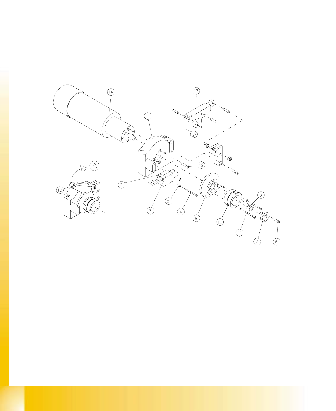
Fig. 9.5.2 Removing the LiftingTable Motor and / or the Lifting Table Proximity Switch
Key
A) Fold the transmission lever up
1) Motor mount 2) Proximity switch "lifting table down"
3) Proximity switch "lifting table up 4) Screws fastening the proximity switch :
2 hexagonal socket head cap screws M3 x
30
5) Reinforcement plate for proximity switch 6) Fasteners for clamping flange:
6 hexagonal socket head cap screws
M4x12
7) Clamping flange 8) Annular spring
9) Cam body 10) Sprocket wheel with lead tapes