HS50_advance_level 1_20200522_221201 (1).pdf - 第36页
06/2002 E dition Studen t Guide H S-50 Advance d I 2 Ov erview 6 Nominal Voltage 2 The Power S upply un it produces the m ost of the supply voltages required to opera te t h e machine The Powe r Suppl y unit can be remov…
Student Guide HS-50 Advanced I 06/2002 Edition
2 Overview
5
2Overview
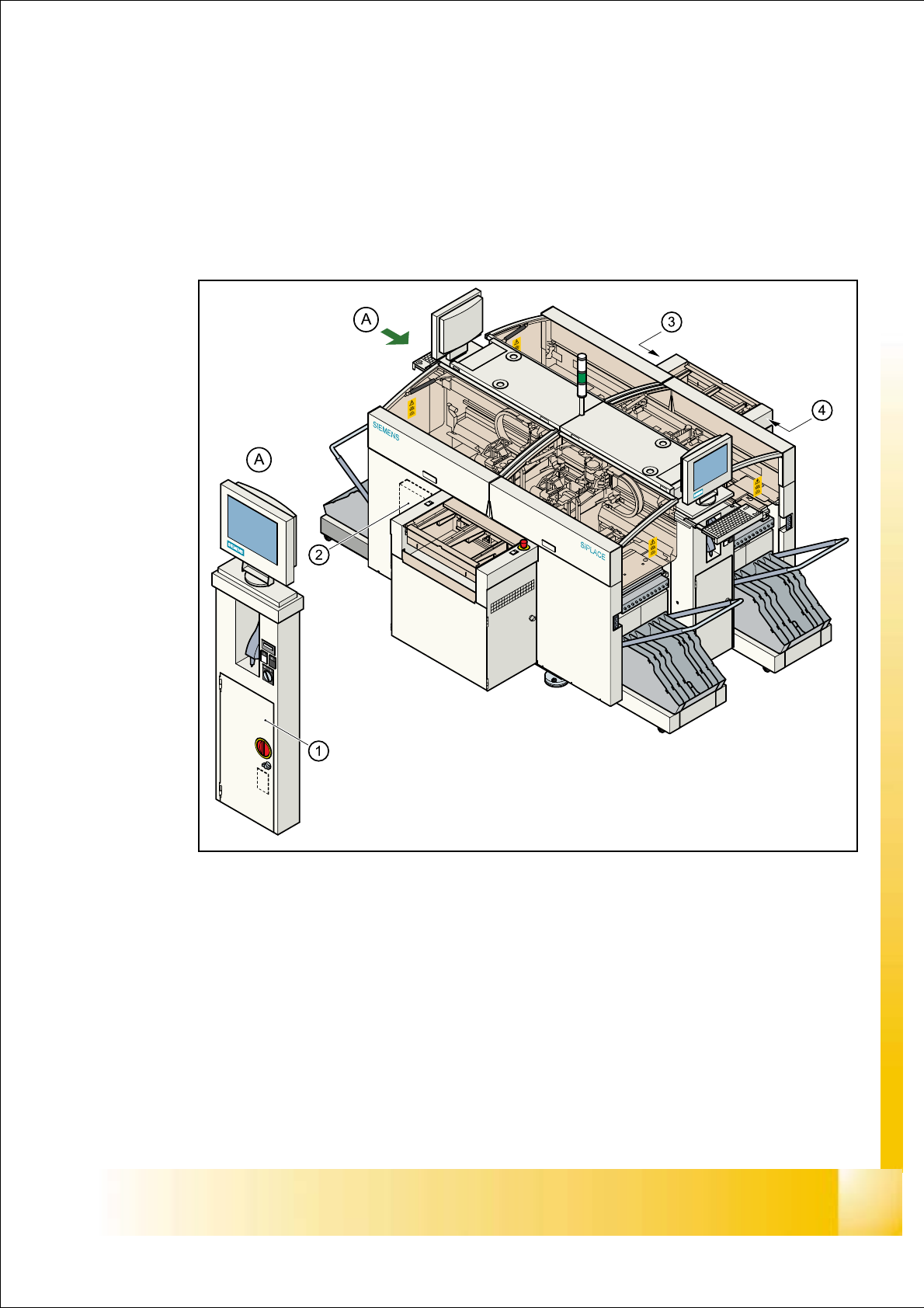
2.1 Electrical Drawer
Fig. 2.1 - 1
Key
(1) Power supply unit (Pos. 1)
(2) Main distribution unit (Pos. 2)
(3) Control unit (Pos. 3)
(4) Servo unit (Pos. 4)
06/2002 Edition Student Guide HS-50 Advanced I
2 Overview
6
Nominal Voltage 2
The Power Supply unit produces
the most of the supply voltages
required to operate the machine
The Power Supply unit can be removed from the
housing for service purposes
Parts of the machine conduct highly danger-
ous voltages, even when the main switch is off.
Please observe the safety guidelines

Student Guide HS-50 Advanced I 06/2002 Edition
2 Overview
7
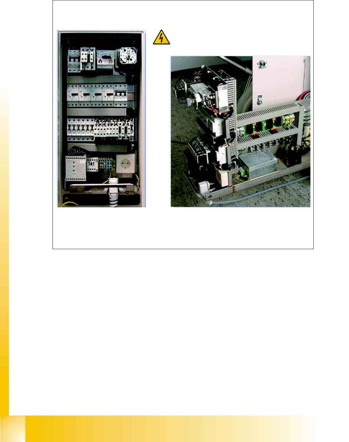
2.1.1 Supply voltages
The power supply unit is located in the left-hand middle section of the placement system. A lock-
able door prevents access to the unit. 2
The power supply unit provides the following supply voltages: 2
– 200 VDC for the servo amplifiers of the x and y axes
– 100 VDC/4 VDC for the servo amplifiers of the star
– 30 VDC for the servo amplifiers the z and dp axes
– 52 VDC for the DC/DC converters in the control unit
– 40 VDC for the component tables and the PCB handling system
– 10 VDC for the component tables
– 3 x 230 VAC for the lifting table motors of the single or dual conveyor (option)
– 230 VAC for the station computer and monitors
For the service socket 2
PLEASE NOTE: The service socket can only be used if the placement system is con-
nected to the main power supply with a 5-conductor cable (L1, L2, L3, N, PE). 2
2.1.2 Voltages on the front panel of the power supply unit
PLEASE NOTE: The placement system must be started in order to take these measurements.
This means that the protective covers and component flaps must be closed and the component
tables docked. The emergency stop button must be released and the Start button pressed. If this
is not the case, the operating voltages will not be switched through to the servo amplifiers, lifting
tables, etc. 2
The inputs to the modules all have odd numbers and the outputs have even numbers. 2
In the case of fuses (F1, etc), the input is always on the underside of the module, whereas with
contactors (SZ1, etc) and motor circuit-breakers (MS1 ...), it is always at the top. 2
230 VAC (Europe) Input 3 x 400 VAC
115 VAC (U. S. A.) Input 3 x 204 VAC
130 VAC (other) Input 3 x 230 VAC
220 VAC (other) Input 3 x 380 VAC
240 VAC (other) Input 3 x 415 VAC