HS50_advance_level 1_20200522_221201 (1).pdf - 第373页
Editi on 06/2002 S tudent Guide HS - 50 Advance d I 10 C omponent Change over T able 8 10.2.2 Undocking the co m pon ent cha ngeove r t able à Click on the STOP PROCE SSING icon in t h e M AIN VIEW m enu. à T he PCB in p…
Student Guide HS-50 Advanced I Edition 06/2002
10 Component Changeover Table
7
10.2 Component changeover tables
10.2.1 Safety instructions for docking and undocking the component changeover
table
WARNING 10
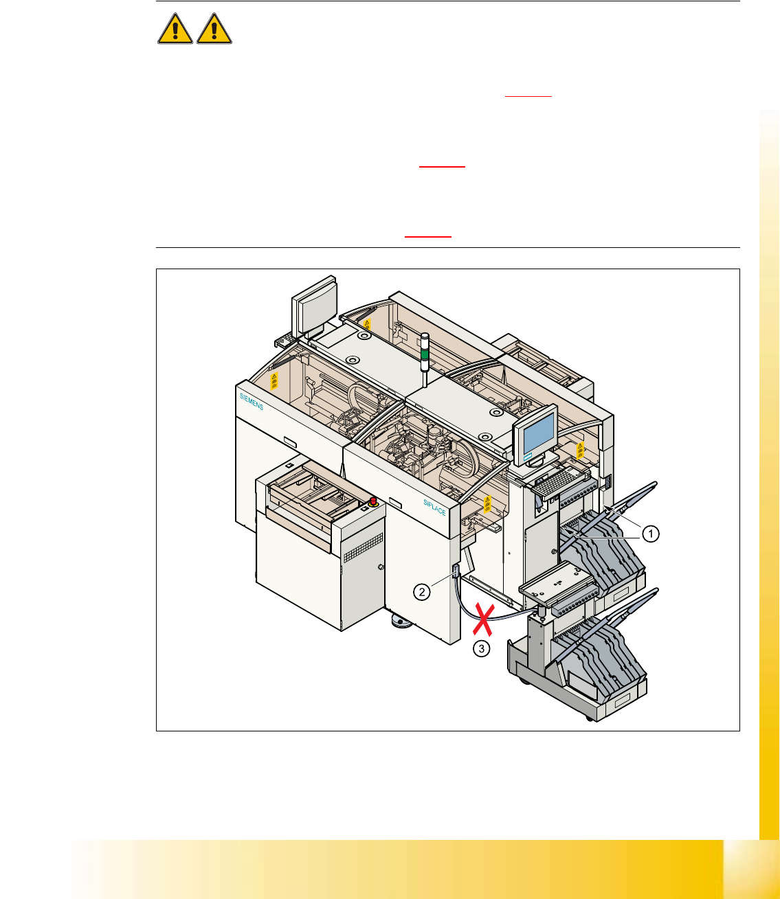
à Never reach into the gaps between the component changeover table and the placement sys-
tem frame while the machine is running (item 1 in Fig. 10.2 - 1
).
à Always check that the component changeover table is docked on the placement system before
connecting or disconnecting the power cable for the component changeover table at the socket
on the placement system (item 2 in Fig. 10.2 - 1
).
à NEVER connect the connecting cable for the component changeover table to the socket on the
placement system and then operate the component table outside the machine via the com-
pressed air control unit (item 3 in Fig. 10.2 - 1).
10
Fig. 10.2 - 1 Safety instructions for the component changeover table

Edition 06/2002 Student Guide HS-50 Advanced I
10 Component Changeover Table
8
10.2.2 Undocking the component changeover table
à
Click on the STOP PROCESSING icon in the MAIN VIEW menu.
à The PCB in progress will be completed. The icons of the SINGLE FUNCTIONS menu will then
be activated.
à Click on the SINGLE FUNCTIONS GANTRY X icon (gantry 1, 2, 3 or 4).
à Click on the GANTRY FUNCTIONS icon.
à From this menu, click on the APPROACH SET-UP POSITION button.
à The selected placement head will move across the PCB transport to prevent it being damaged
when the component table is changed.
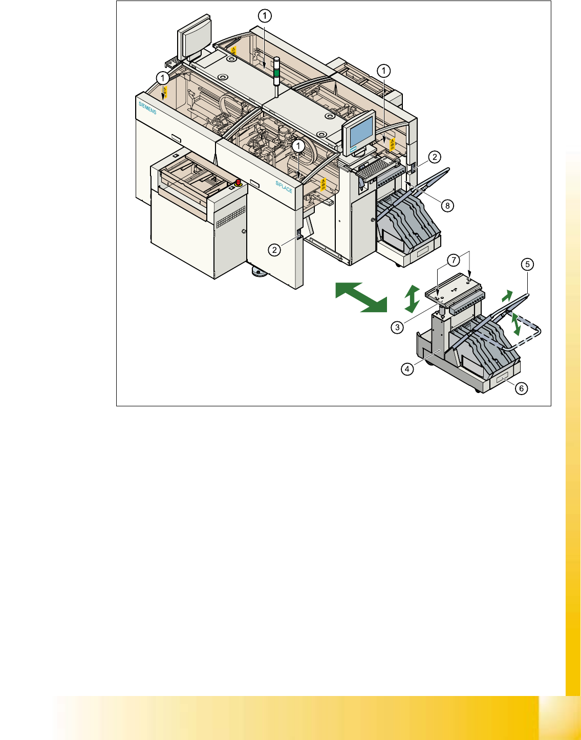
à Fold up the protective cover of the selected gantry.
à Lift up the clip (item 5) to lock the raised component table bed in its top end position.
à Lift the flap over the button (item 1).
à Hold down the button (item 1) for raising the component table bed (item 3) until the component
table bed reaches its top end position.
à Unplug the component changeover table (item 2) from the placement system.
à Remove the component changeover table.
Student Guide HS-50 Advanced I Edition 06/2002
10 Component Changeover Table
9
10
Fig. 10.2 - 2 Changing the component changeover table
(1) Button for raising and lowering the component table plate
(2) Plug for connecting the component changeover table cable
(3) Component table bed, can be raised and lowered
(4) Component changeover table
(5) Bracket
(6) Used tape container
(7) Centering holes for the centering pins
(8) Gap between the component table and machine stand