HS50_advance_level 1_20200522_221201 (1).pdf - 第378页
S tud ent Guid e HS-50 A dvanced I Editi on 06/2 002 10 Co mpon ent Cha ngeov er T ab le 13 Key to Fig. 10.4.1: 1) Componen t changeover table (without f eede rs) 2) F eeder modul es or dummy modul es ** ) 3) Rem ov able…
Edition 06/2002 Student Guide HS-50 Advanced I
10 Component Changeover Table
12
10.4 Overview of Mechanical Construction
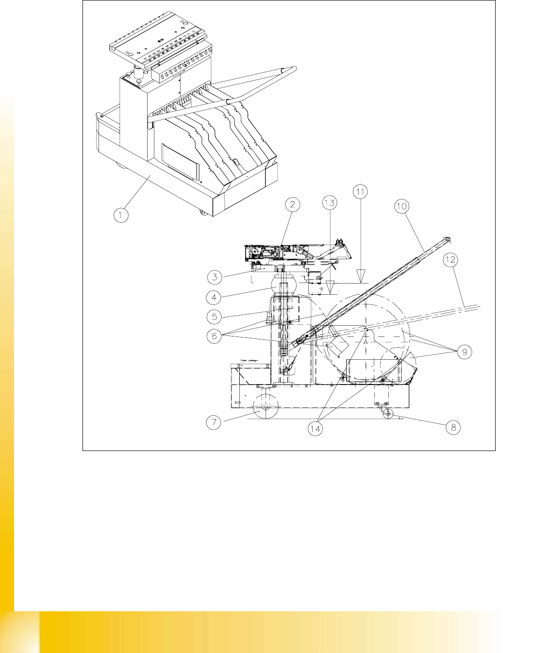
Fig. 10.4.1 Overview: Layout and Exchangeable Parts of the Changeover Table HS-50

Student Guide HS-50 Advanced I Edition 06/2002
10 Component Changeover Table
13
Key to Fig. 10.4.1:
1) Component changeover table (without feeders) 2) Feeder modules or dummy
modules **)
3) Removable component table 4) Bellows cylinder for height
adjustment *)
5) Communications unit, movable component table*) 7) Cable for component table with
plug-and-socket connections *)
7) 2 Fixed castors *) 8) 2 Guide castors *)
9) Insertable tape reels: 7", 15 ", 17", 19 " 10) Handle to swivel or hold in "Table =
top" position
11) Component table in "top" position" 12) Handle to swivel or hold in "Table =
bottom" position
13) Component table in "bottom" position 14) Knockout spindle for tape reels (if
needed)
*) Item No.: see Section 10.3
**) Option, Item No.:
for feeder modules -> see SIPLACE Service Manual, Chapter "Feeder Modules".
for dummy modules -> Item No. 00345462-01

Edition 06/2002 Student Guide HS-50 Advanced I
10 Component Changeover Table
14
10.5 Resolving Problems
10.5.1 Preparatory Steps
à Cut the tapes between the front of the module and the empty-tape duct.
à Clock the tapes back.
à Pull off the connector of the "Cable/Component table" at the relevant position on the machine
base.
à Move the component changeover table out of the machine as described in the User Manual.
à The component changeover table is then at the position "TOP" -> handle position, see Fig.
10.4.1.
à If another component changeover table is available:
à Pull out the plug-and-socket connections of all of the feeder modules on the component
changeover table.
à Move the module, including the reel, to the new component changeover table.
à If no other component changeover table is available, proceed on the basis of the work to be
performed:
– When exchanging the bellows cylinder:
Take the feeder modules from the changeover table and place them on a clean surface. In
this case, the tape reels can remain in the container.
– When exchanging the guide castors and fixed castors:
Same as above. In addition, remove all of the tape reels from the container and put them
down in order.
– When exchanging the "Cable/component table" and the communications unit:
The feeder modules do not have to be dismantled.