HS50_advance_level 1_20200522_221201 (1).pdf - 第380页
S tud ent Guid e HS-50 A dvanced I Editi on 06/2 002 10 Co mpon ent Cha ngeov er T ab le 15 10.5 .2 Ex changi ng the Bello ws Cyl inder DANGER Adhe r e t o the instructions in the DANGER text in Section 10.1 . Part…

Edition 06/2002 Student Guide HS-50 Advanced I
10 Component Changeover Table
14
10.5 Resolving Problems
10.5.1 Preparatory Steps
à Cut the tapes between the front of the module and the empty-tape duct.
à Clock the tapes back.
à Pull off the connector of the "Cable/Component table" at the relevant position on the machine
base.
à Move the component changeover table out of the machine as described in the User Manual.
à The component changeover table is then at the position "TOP" -> handle position, see Fig.
10.4.1.
à If another component changeover table is available:
à Pull out the plug-and-socket connections of all of the feeder modules on the component
changeover table.
à Move the module, including the reel, to the new component changeover table.
à If no other component changeover table is available, proceed on the basis of the work to be
performed:
– When exchanging the bellows cylinder:
Take the feeder modules from the changeover table and place them on a clean surface. In
this case, the tape reels can remain in the container.
– When exchanging the guide castors and fixed castors:
Same as above. In addition, remove all of the tape reels from the container and put them
down in order.
– When exchanging the "Cable/component table" and the communications unit:
The feeder modules do not have to be dismantled.

Student Guide HS-50 Advanced I Edition 06/2002
10 Component Changeover Table
15
10.5.2 Exchanging the Bellows Cylinder
DANGER
Adhere to the instructions in the DANGER text in Section 10.1.
Parts of your body may be crushed, pinched or severed by the component changeover table!!10
The "Preparatory Steps" (see Section 10.5.1) have been executed.
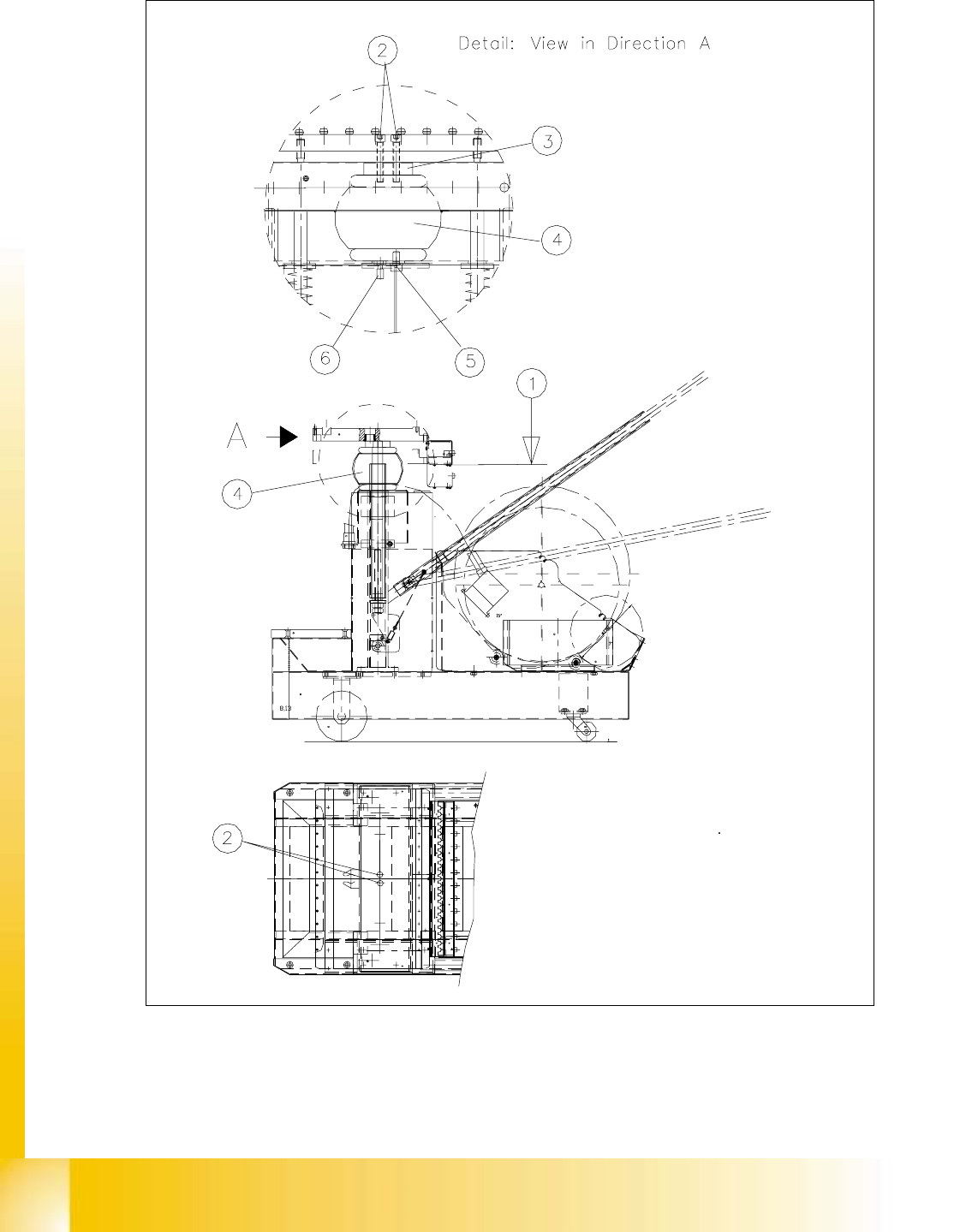
à Make certain that the component table is in the "TOP" position so that the bellows cylinder can
be installed and removed.
à This corresponds to the condition of the component changeover table after it has been moved
out of the machine, as shown in Fig. 10.5.1 -> 1.
à Disconnect the pneumatic hose at the quick-release coupling of the bellows cylinder (see Fig.
10.5.1 -> 6). The 2nd pneumatic hose (for 2.3 bar) is not connected.
à Undo the screws fastening the bellows cylinder from the component top and bottom (total of 3
screws, see: Fig. 10.5.1 -> 2, 5, 7, size 6 Allen wrench). During this process, take the washer
enclosed.
à Regardless of the bellows cylinder, the component table top is securely held in the "TOP" po-
sition mechanically:
Remove the bellows cylinder.
à Insert the new bellows cylinder (Item No.: see Section 10.3) and fasten the cylinder securely
from top and bottom (see Fig. 10.5.1 -> 2, 4, 5).
NOTE:
When the new cylinder is installed, the spacer disk (see Fig. 10.5.1 -> 3) must be re-in-
stalled. 10
à Connect the 5 bar pneumatic hose to the quick-release coupling of the bellows cylinder and
tighten the hex nut (see Fig. 10.5.1 -> 6).
à If you do not have to exchange any further parts, perform the "Final Steps" (see Section
10.5.6).
Key to Fig. 10.5.1:
1) Component table in top position 2) Fasteners for bellows cylinder:
= open 2 Socket hex cap screws M 8 x 50
3) Component table spacer disk 4) Bellows cylinder
5) Bellow cylinder fasteners 6) Quick-release coupling, compressed air supply,
2 washers, 8.4 DIN 125-A 5 bar
2 Socket hex cap screws M 8 x 16
Edition 06/2002 Student Guide HS-50 Advanced I
10 Component Changeover Table
16
Fig. 10.5.1 Exchanging the Bellows Cylinder