HS50_advance_level 1_20200522_221201 (1).pdf - 第387页
Editi on 06/2002 S tudent Guide HS - 50 Advance d I 10 C omponent Change over T able 22 10.6 CAN - Bus Copple r Compo nent T a ble Jumper 10 fi g. 10 .6 .1 CA N - bu s co pp ler com p onen t ta bl e 10 q

Student Guide HS-50 Advanced I Edition 06/2002
10 Component Changeover Table
21
à Perform the "Preparatory Steps" (see Section 10.5.1).
à Undo the cable lug for the grounding cable on the back of the communications unit (see Fig.
10.5.4 -> 3). During the process, save the contact lock washer and the spring lock washer un-
der it.
à Unplug the connector for the interface cable and power supply cable on the back of the com-
munications unit (see Fig. 10.5.4 -> 4 and 5).
à Holding the communications unit securely, loosen the screws fastening this unit, at the left and
right on the table plate (Allen wrench, size 4: see Fig. 10.5.4).
à Visually inspect the edge guard (see Fig. 10.5.4 -> 6). Install a new one if it is damaged (Item
No.: see Section 10.3).
à Place the new communications unit (Item No.: see Section 10.3) to the table plate and tighten
the screws to fasten it.
à Fasten the cable lug on the grounding cable to the back of the communications unit, on the
housing. During the process, insert the contact lock washer and the spring lock washer.
à Make the plug-and-socket connection of component table interface and power supply cable on
the control board of the communications unit (see Fig. 10.5.4 -> 4 and 5).
à Make certain the component table cable is run in the cable harness (= strain relief) and that the
hex nut on the bottom (counter nut PG 16 MS) has been tightened (Fig. 10.5.3 -> 7).
10.5.6 Final Steps
à Check the contact surface for the feeder modules on the component table:
à If necessary, clean the surface as described in the User Manual in the chapter "Maintenance".
à Place the feeder modules on the component table in accordance with the specifications for set-
up optimization.
à Connect all feeder modules to the relevant jack of the communications unit (component table
termination panel).
à If there is an external set-up location available, check the allocation of feeder module and com-
ponent (component bar code scanner) and insert the tapes.
à Check whether the track of the sliding handle is sufficiently greased. If necessary, perform this
step as described in the User Manual, chapter "Maintenance".
à Move the component changeover table into the machine and connect it.
à Make the plug-and-socket connection of the "Cable/component table" at the machine base.
à If this has not been done yet, insert the tapes now and check the allocation of feeder module
and component (component bar code scanner).
à Clock / transport the first component into the pick-up position. Check at the front of the module
to see if all tapes move smoothly into the empty-tape duct.
à If the SITEST program is necessary to check component table functions, note the DANGER
notice regarding the SITEST program (see Section 10.1). Start the SITEST program.
à Start the placement process.
Edition 06/2002 Student Guide HS-50 Advanced I
10 Component Changeover Table
22
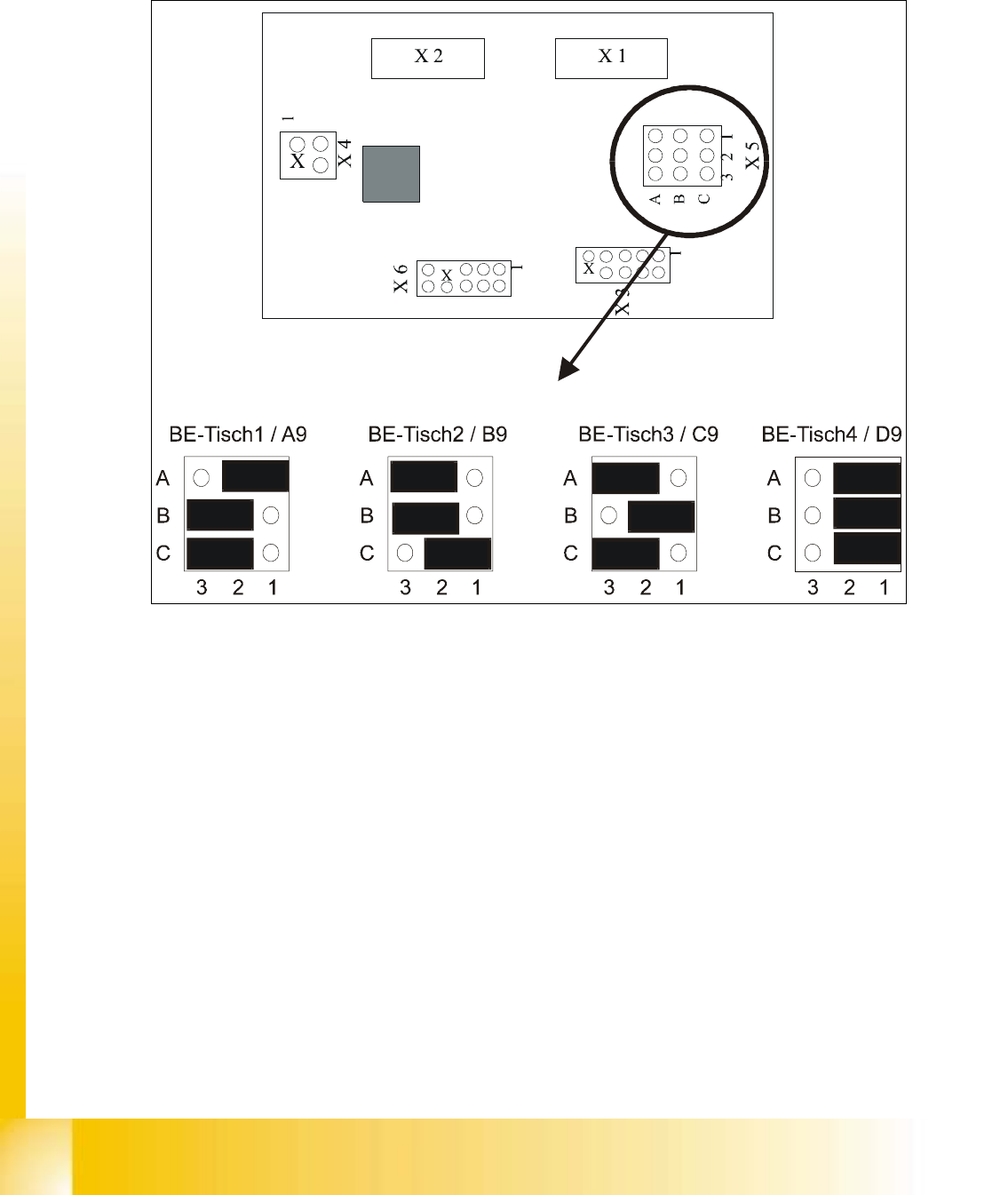
10.6
CAN - Bus Coppler Component Table Jumper
10
fig. 10.6.1 CAN - bus coppler component table
10
q

11 Pneumatic Cutter and
Empty-Tape Duct