HS50_advance_level 1_20200522_221201 (1).pdf - 第39页
Studen t Guide HS-50 A dvanced I 06/200 2 Edition 2 Overview 9 Module Design at i on Clamp s Vo l t a g e s X1 connec ting termi nal panel power sup ply U, V, W 3 x 204 VAC / 3 x 3 80 VAC / 3 x 400 VAC / 3 x 4 15 VAC BU1…
06/2002 Edition Student Guide HS-50 Advanced I
2 Overview
8
2
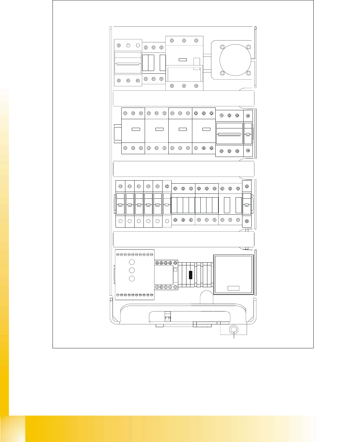
Fig. 2.1 - 2 Voltages on the front panel of the power supply unit
246
135
F3
135
246
SZ1
K14
K12
K11
135
246
MS1A
MS1
S1
MS5 MS6MS4MS3
135
2 64 2 64
1 53 31 5
42 6 624
513
F4
426
31 5
F10F9F8F7F6F5
111111
222 222
F1
2
1
SZ2 SZ3 SZ23
246
135135
2462 46
1
3 5
K232
K234
K34
K33
K32
K31
K21
K22
K23
K24
SSK
1 375
4268
A1+
A2-
SZ4
X1
VUWW
PE
PE
N
BU1
M8
F11
2
1
54 6614 24 4434X4 X6L-
13L+ X3X1 X5 533323 43 65
Netz
Power
Channel 1
Kanal 1
Channel 2
Kanal 2
Student Guide HS-50 Advanced I 06/2002 Edition
2 Overview
9
Module Designation Clamps Voltages
X1
connecting terminal panel
power supply
U, V, W
3 x 204 VAC / 3 x 380 VAC /
3 x 400 VAC / 3 x 415 VAC
BU1
service socket 115 VAC / 220 VAC / 230VAC / 240 VAC
S1
main switch
1, 3, 5 u.
2, 4, 6
3 x 204 VAC / 3 x 380 VAC /
3 x 400 VAC / 3 x 415 VAC
MS1
motor protective switch
1, 3, 5 u.
2, 4, 6
3 x 204 VAC / 3 x 380 VAC /
3 x 400 VAC / 3 x 415 VAC
SZ1
main contactor
1, 3, 5 u.
2, 4, 6
3 x 204 VAC / 3 x 380 VAC
3 x 400 VAC / 3 x 415 VAC
MS3
MS4
MS5
MS6
motor protective switch
PCB conveyor 1
motor protective switch
PCB conveyor 2 (option)
1, 3, 5 u.
2, 4, 6
1, 3, 5 u.
2, 4, 6
3 x 230 VAC
3 x 230 VAC
3 x 230 VAC
3 x 230 VAC
SZ2
contactor
1, 3, 5
2, 4, 6
3 x 140 VAC
3 x 140 VAC
SZ3
contactor
1, 3, 5
2, 4, 6
3 x 140 VAC
3 x 140 VAC
SZ23
contactor
1, 3, 5
2, 4, 6
3 x 140 VAC
3 x 140 VAC
SZ4
contactor
A1 (+) - A2 (-)
1, 2
3, 4
5, 6
24 VDC
24 VDC against ground
24 VDC against ground
24 VDC against ground
SSK
protective contactor
combination
L+, X3, X5 24 VDC against ground
F1
fuse
service socket
1, 2
115 VAC / 220 VAC
230 VAC / 240 VAC
against N on the connecting terminal panel 1
F3
fuse
board net
1, 3, 5
2, 4, 6
3 x 230 VAC
F4
fuse
x- / y- axis
1, 3, 5
2, 4, 6
3 x 140 VAC
F5
fuse
star - axis
1, 2 100 VDC against minus of rectifier V3.
F6
fuse
z- and dp - axis
1, 2 30 VDC against minus of rectifier of V4.
F7
fuse
component table (feeder)
1, 2
38 VDC against minus of rectifier V5.
06/2002 Edition Student Guide HS-50 Advanced I
2 Overview
10
2.2 Control Cage
2.2.1 Power supply module
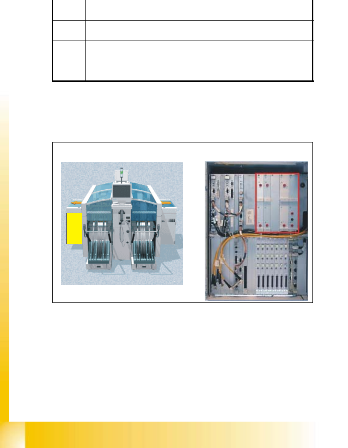
Fig. 2.2 - 1 Control Cageand power supply unit
After the main switch has been activated, the DC/DC converter in the control unit is supplied with
60 VDC from the power supply unit.
(1) +/- 12 VDC for the digital electronics
(2) +/-15 VDC for the analog electronics
(3) +24 VDC to supply the control circuits, relays, etc.
(4) +5 VDC / 20 A for the digital electronics in the individual sectors
(5) 50 VDC input for the power supply
(6) +5 VDC / 60 A for the digital electronics in the control unit
F8
fuse
PCB conveyor
1, 2
38 VDC against minus of rectifier V5.
F9
fuse
component table (logic)
1, 2
8 VDC against minus of rectifier V6.
F10
fuse
control unit
1, 2
52 VDC against minus of rectifier V7.
F11
fuse
in rush limiter
1, 2
30 VDC against minus of rectifier V8.
Left View (main operator controls) Power Supply modules
(1)(2) (3)
(4)
(5)
(6)