HS50_advance_level 1_20200522_221201 (1).pdf - 第395页
Editi on 06/2002 S tudent Guide HS - 50 Advance d I 1 1 Pneumat ic Cutter and Emp ty-T ap e Duct 8 11.4 Overvie w of Mec hanical La y o ut 11 Fig . 11.4. 1 O v ervi ew of Pne umat ic Cut t e r V ers ion 04 and E mpty-T a…

Student Guide HS-50 Advanced I Edition 06/2002
11 Pneumatic Cutter and Empty-Tape Duct
7
- 2 Fixing pedestal for cable tie 00318666-01 2 altogether
adhesive type
- 2 Cable tie (W = 2,4mm, L = 92mm) 00805140-01
- 1 If needed: Adhesive label (with text) 00324065-04 German and English
- 1 If needed: Adhesive label (with text) on request EU languages
- 1 If needed: Adhesive label: Triangular
warning symbol "Hand injury" 00335957-01
11.3 Tools, Expendable Materials, Documentation
– Thick protective gloves
– Set of socket wrenches, cross-slotted screwdriver size 4,
– Open-end wrench, width across flats 10; slotted screwdriver size 1
– Torque wrench
– Diagonal cutter
– Sliding caliper
– Feeler gauge 0.05mm; 1.0mm; 1.5mm, 2.0mm; 2.50mm
– Straight-edge (for check of tape deflector)
– Mounting plate, Item no.: 00312731-01
– 2 large parallel clamps (or mounting plate, see above)
– Flat, sturdy work bench to fasten the removed cutter (or mounting plate, see above)
– Loctite no. 234,, Item no.: 00334892-01
– Molykote paste, Item no. 02100335-01, 250 g, (preferred) or
ISOFLEX TOPAS NCA 52, Item. no. 00330850-01, tube 50 g
– Water-insoluble, fine-tip marker
– A dry and clean cloth
– Operating manual for SITEST program, Version 501.xx, English, Item No. 00191417-01
Edition 06/2002 Student Guide HS-50 Advanced I
11 Pneumatic Cutter and Empty-Tape Duct
8
11.4 Overview of Mechanical Layout
11
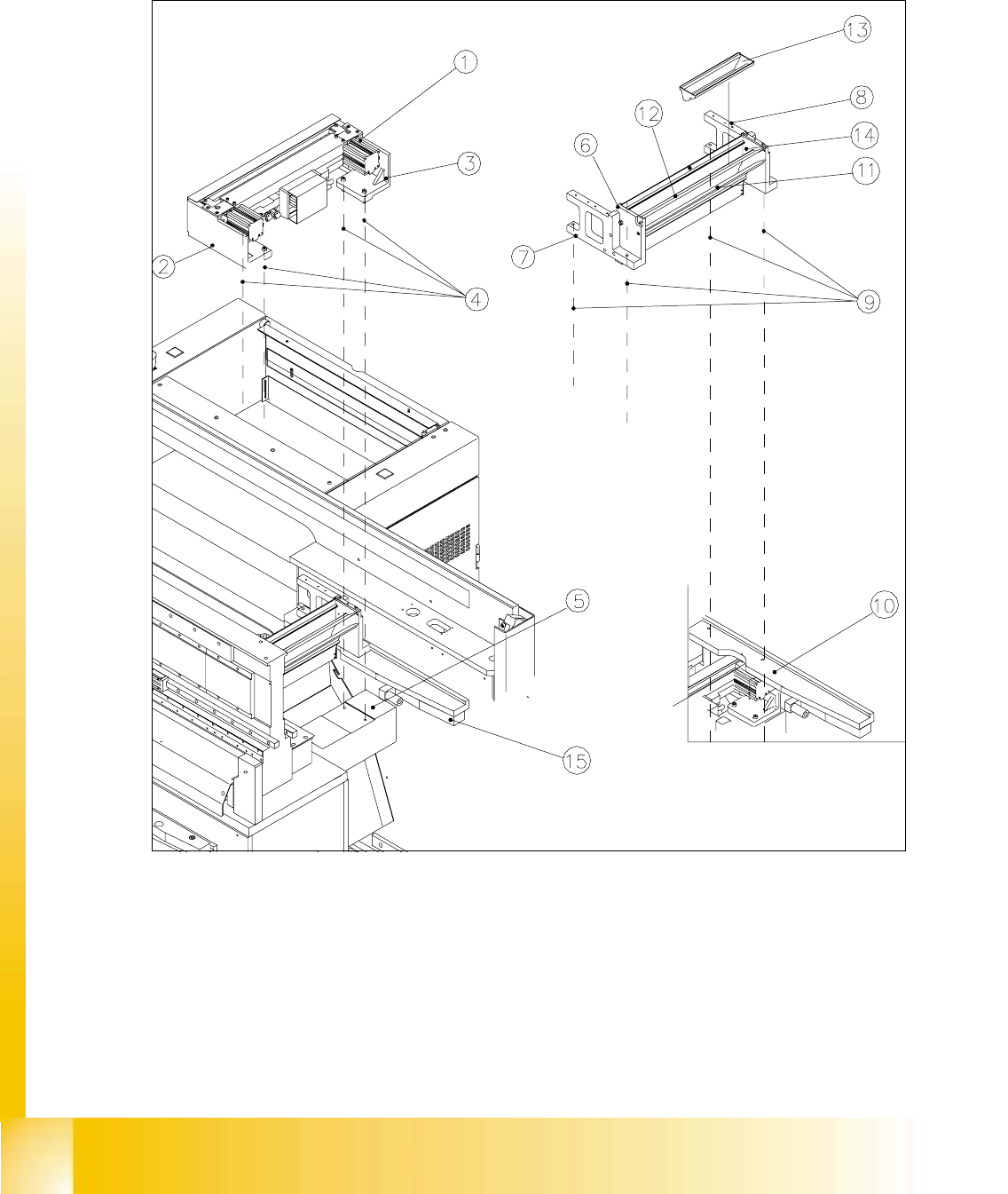
Fig. 11.4.1 Overview of Pneumatic Cutter Version 04 and Empty-Tape Duct Version 03

Student Guide HS-50 Advanced I Edition 06/2002
11 Pneumatic Cutter and Empty-Tape Duct
9
Key to Fig. 11.4.1:
1. Pneumatic cutter HS-50
2. Retaining bracket for cutter, left
3. Retaining bracket for cutter, right
4. Fastening of the cutter,
2 socket hex head cap screws M6 x 25 each on left and right *)
Re-install any disks or plates that were previously removed.
5. Mounting surface for cutter on the machine frame
6. Empty-tape duct assembly
7. Side panel (left) of the empty-tape duct
8. Side panel (right) of the empty-tape duct
9. Fastening of "empty-tape duct assembly":
2 socket hex head cap screws M 4 x 16 each on left and right
10. Mounting surface for the "empty-tape duct assembly" on the machine frame
11. Baffle, inside
12. Baffle, outside
13. Reject box for nozzles
14. Reject box (profile)
15. Stop buffer assembly on left- and right-hand side of the machine frame,
Fastening: 2 socket hex head cap screws M8 each on left and right
*) Loosen these screws only when removing/installing the cutter (see Section 11.6.1.1).