HS50_advance_level 1_20200522_221201 (1).pdf - 第396页
S tud ent Guid e HS-50 A dvanced I E dition 06/2 002 1 1 P neumatic Cutt er and Empty- T ape Du ct 9 Key t o Fi g. 11 .4 .1: 1. Pneu matic cutter HS-50 2. Re taining br a ck et f or cutter , left 3. Re taining br acket f…
Edition 06/2002 Student Guide HS-50 Advanced I
11 Pneumatic Cutter and Empty-Tape Duct
8
11.4 Overview of Mechanical Layout
11
Fig. 11.4.1 Overview of Pneumatic Cutter Version 04 and Empty-Tape Duct Version 03

Student Guide HS-50 Advanced I Edition 06/2002
11 Pneumatic Cutter and Empty-Tape Duct
9
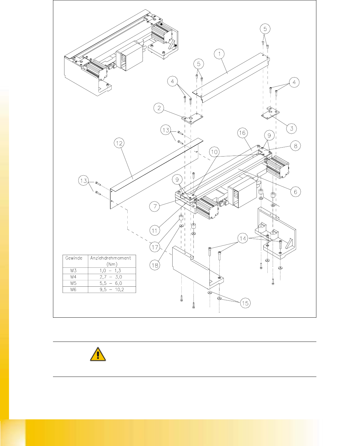
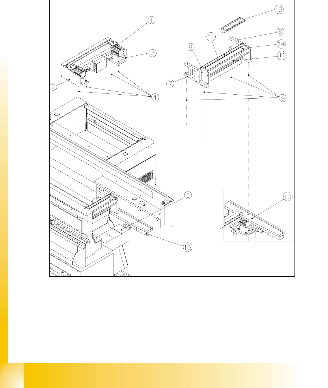
Key to Fig. 11.4.1:
1. Pneumatic cutter HS-50
2. Retaining bracket for cutter, left
3. Retaining bracket for cutter, right
4. Fastening of the cutter,
2 socket hex head cap screws M6 x 25 each on left and right *)
Re-install any disks or plates that were previously removed.
5. Mounting surface for cutter on the machine frame
6. Empty-tape duct assembly
7. Side panel (left) of the empty-tape duct
8. Side panel (right) of the empty-tape duct
9. Fastening of "empty-tape duct assembly":
2 socket hex head cap screws M 4 x 16 each on left and right
10. Mounting surface for the "empty-tape duct assembly" on the machine frame
11. Baffle, inside
12. Baffle, outside
13. Reject box for nozzles
14. Reject box (profile)
15. Stop buffer assembly on left- and right-hand side of the machine frame,
Fastening: 2 socket hex head cap screws M8 each on left and right
*) Loosen these screws only when removing/installing the cutter (see Section 11.6.1.1).