HS50_advance_level 1_20200522_221201 (1).pdf - 第397页
Editi on 06/2002 S tudent Guide HS - 50 Advance d I 1 1 Pneumat ic Cutter and Emp ty-T ap e Duct 10 F ig. 11 .4 .2 Over view : R emov in g and In stal li ng t he C over P lat e a nd t he T a pe D efle ct or CA UTION Tigh…

Student Guide HS-50 Advanced I Edition 06/2002
11 Pneumatic Cutter and Empty-Tape Duct
9
Key to Fig. 11.4.1:
1. Pneumatic cutter HS-50
2. Retaining bracket for cutter, left
3. Retaining bracket for cutter, right
4. Fastening of the cutter,
2 socket hex head cap screws M6 x 25 each on left and right *)
Re-install any disks or plates that were previously removed.
5. Mounting surface for cutter on the machine frame
6. Empty-tape duct assembly
7. Side panel (left) of the empty-tape duct
8. Side panel (right) of the empty-tape duct
9. Fastening of "empty-tape duct assembly":
2 socket hex head cap screws M 4 x 16 each on left and right
10. Mounting surface for the "empty-tape duct assembly" on the machine frame
11. Baffle, inside
12. Baffle, outside
13. Reject box for nozzles
14. Reject box (profile)
15. Stop buffer assembly on left- and right-hand side of the machine frame,
Fastening: 2 socket hex head cap screws M8 each on left and right
*) Loosen these screws only when removing/installing the cutter (see Section 11.6.1.1).

Student Guide HS-50 Advanced I Edition 06/2002
11 Pneumatic Cutter and Empty-Tape Duct
11
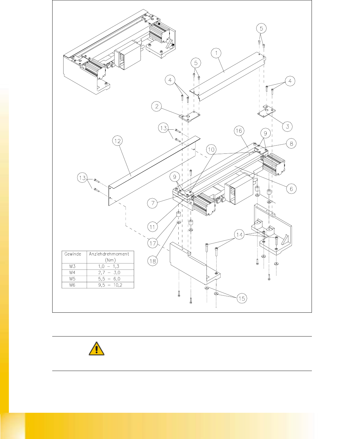
Key to Fig. 11.4.2:
1. Cover holder
2. Cover plate holder, left
3. Cover plate holder, right
4. Screws to fasten the cover plate holder:
2 cape screws M4 x 8 DIN 84 or 2 countersunk srews M4 x 6 DIN 965 each
5. Screws to fasten the cover plate (incl. tape deflector) -> do not loosen
6. Tape deflector (with movable blade underneath them)
7. Tape deflector holder, left
8. Tape deflector holder, right
9. Screws to fasten the tape deflector holders: 2 socket hex head cap screws M4 x 35
each on LH and RH
10. Screws to fasten the tape deflector: 1 countersunk screw each -> do not loosen
11. Holddowns (at left and right) with spacers inserted underneath them
12. Deflector plate
13. Screws to fasten the deflector plate: 4 socket hex head cap screws M4 x 8
14. Screws to fasten the cutter on the machine frame
4 socket hex head cap screws M 6 x 25 *)
15. Any disks or plates installed underneath them
16. Stationary blade
17. Rubber-metal vibration damper
18. Any disks and spring washer installed underneath them
*) Loosen these screws only when removing/installing the cutter (see Section 11.6.1).