HS50_advance_level 1_20200522_221201 (1).pdf - 第399页
Editi on 06/2002 S tudent Guide HS - 50 Advance d I 1 1 Pneumat ic Cutter and Emp ty-T ap e Duct 12 F ig. 11 .4 .3 Cros s S ect io n o f E mpty -Ta pe Du ct an d Pne uma tic Cu tte r

Student Guide HS-50 Advanced I Edition 06/2002
11 Pneumatic Cutter and Empty-Tape Duct
11
Key to Fig. 11.4.2:
1. Cover holder
2. Cover plate holder, left
3. Cover plate holder, right
4. Screws to fasten the cover plate holder:
2 cape screws M4 x 8 DIN 84 or 2 countersunk srews M4 x 6 DIN 965 each
5. Screws to fasten the cover plate (incl. tape deflector) -> do not loosen
6. Tape deflector (with movable blade underneath them)
7. Tape deflector holder, left
8. Tape deflector holder, right
9. Screws to fasten the tape deflector holders: 2 socket hex head cap screws M4 x 35
each on LH and RH
10. Screws to fasten the tape deflector: 1 countersunk screw each -> do not loosen
11. Holddowns (at left and right) with spacers inserted underneath them
12. Deflector plate
13. Screws to fasten the deflector plate: 4 socket hex head cap screws M4 x 8
14. Screws to fasten the cutter on the machine frame
4 socket hex head cap screws M 6 x 25 *)
15. Any disks or plates installed underneath them
16. Stationary blade
17. Rubber-metal vibration damper
18. Any disks and spring washer installed underneath them
*) Loosen these screws only when removing/installing the cutter (see Section 11.6.1).
Edition 06/2002 Student Guide HS-50 Advanced I
11 Pneumatic Cutter and Empty-Tape Duct
12
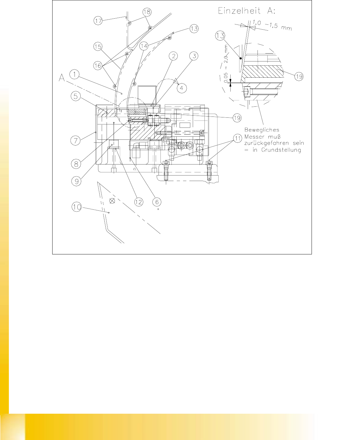
Fig. 11.4.3 Cross Section of Empty-Tape Duct and Pneumatic Cutter

Student Guide HS-50 Advanced I Edition 06/2002
11 Pneumatic Cutter and Empty-Tape Duct
13
Key to Fig. 11.4.3 (left):
1. Empty-tape duct assembly
2. Cover plate
3. Screws fastening the cover plate
4. Direction to remove the cover plate, fastening: 4 socket hex head cap screws M4 x 8
5. Stationary blade, fastened with: 2 socket hex head cap screws M6 x 35
6. Protective sheet (remains mounted)
7. Deflector plate (deflects small chips of tape)
8. 2 socket hex head cap screws M4 x 8
9. Screws fastening the articulated joint to the movable blade (see also Fig. 11.6.4):
10. Rubber-metal vibration damper (4 x ), each fastened with
1 socket hex head cap screw M 4 x 20 (top),
1 socket hex head cap screw M 4 x 35 (bottom)
and any disk and spring washer (4 DIN 127-A) installed underneath them
11. Tape waste chute (baffle in the machine frame)
12.Screws fastening the cutter, 2 socket hex head cap screws M 6 x 25
13. Baffle, inside
14. Screws M4 x 20, self-tapping
15. Baffle, outside
16. Screws M4 x 20, self-tapping
17. Reject box (profile)
18. Screws M4 x 16, self-tapping
19. Tape deflector